
A runflat tire with sidewall-reinforcing inserts

a technology of sidewall reinforcement and runflat tire, which is applied in the field of runflat tire, can solve the problems of horizontal crack or slit through the sidewall reinforcement insert, rendering the runflat tire non-functional for its intended purpose, increasing the weight and size etc., and achieves the effect of increasing the complexity of the tire design and increasing the durability of the runflat tir

Active Publication Date: 2018-02-08
BRIDGESTONE AMERICAS TIRE OPERATIONS LLC
View PDF11 Cites 0 Cited by
  • Summary
  • Abstract
  • Description
  • Claims
  • Application Information

AI Technical Summary

Benefits of technology

The invention is a new type of tire that can run flat for a longer time without losing strength. It uses reinforcing inserts on the sides of the tire to increase its durability. This improvement makes the tire stronger even when it is not being inflated. The design of the tire remains simple and will require minimal changes to current production methods.

Problems solved by technology

While functioning in the zero psi state, eventually the stress of bearing a vehicle load without tire inflation pressure results in a horizontal crack or slit through the sidewall-reinforcing insert.
Eventually the slit extends across the entire thickness of the insert resulting in a failure condition, rendering the run-flat tire non-functional for its intended purpose.
Some run-flat tire designs directed to increasing run-flat durability include increasing the thickness of the insert; however, this has the disadvantage of increasing the run-flat tire weight and size.
Additionally, increasing the amount of rubber to reinforce the sidewalls can contribute to heat build-up, which is a contributing factor to tire failure.
These additional components increase the complexity of the tire design and the tire assembly process, resulting in increased production time and increased costs.
Many of the sidewall reinforcing components are integrated into other regions of the tire and may affect other non-sidewall-reinforcing components of the tire, which, in some cases, may affect certain aspects of the overall performance of the tire.
Such configurations further increase the complexity of the tire design and tire assembly process, thereby resulting in more time delays and further costs.

Method used


Image

  • A runflat tire with sidewall-reinforcing inserts
  • A runflat tire with sidewall-reinforcing inserts
  • A runflat tire with sidewall-reinforcing inserts

Examples


Embodiment Construction

[0039]While the specification concludes with claims defining the features of the invention that are regarded as novel, it is believed that the invention will be better understood from a consideration of the following description in conjunction with the drawing figures, in which like reference numerals are carried forward. It is to be understood that the disclosed embodiments are merely exemplary of the invention, which can be embodied in various forms.

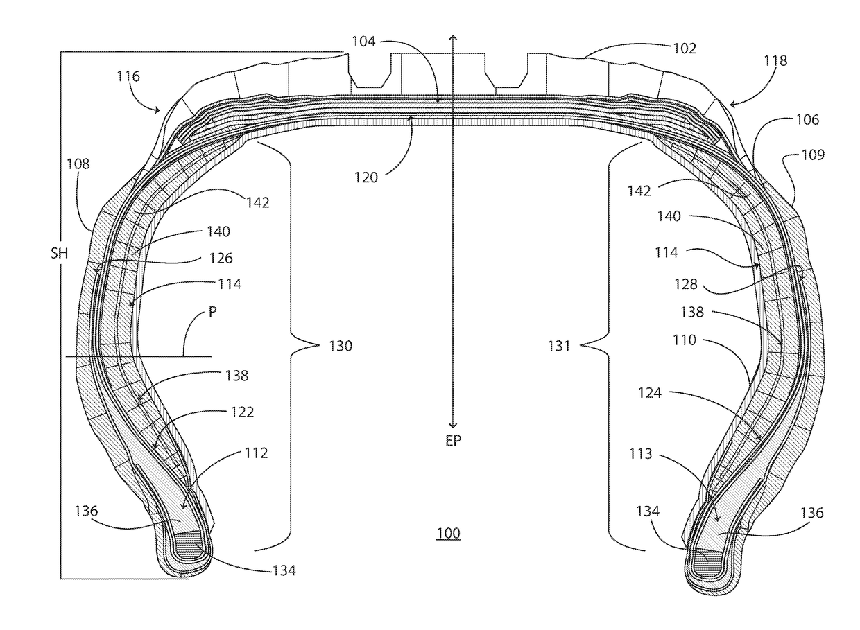
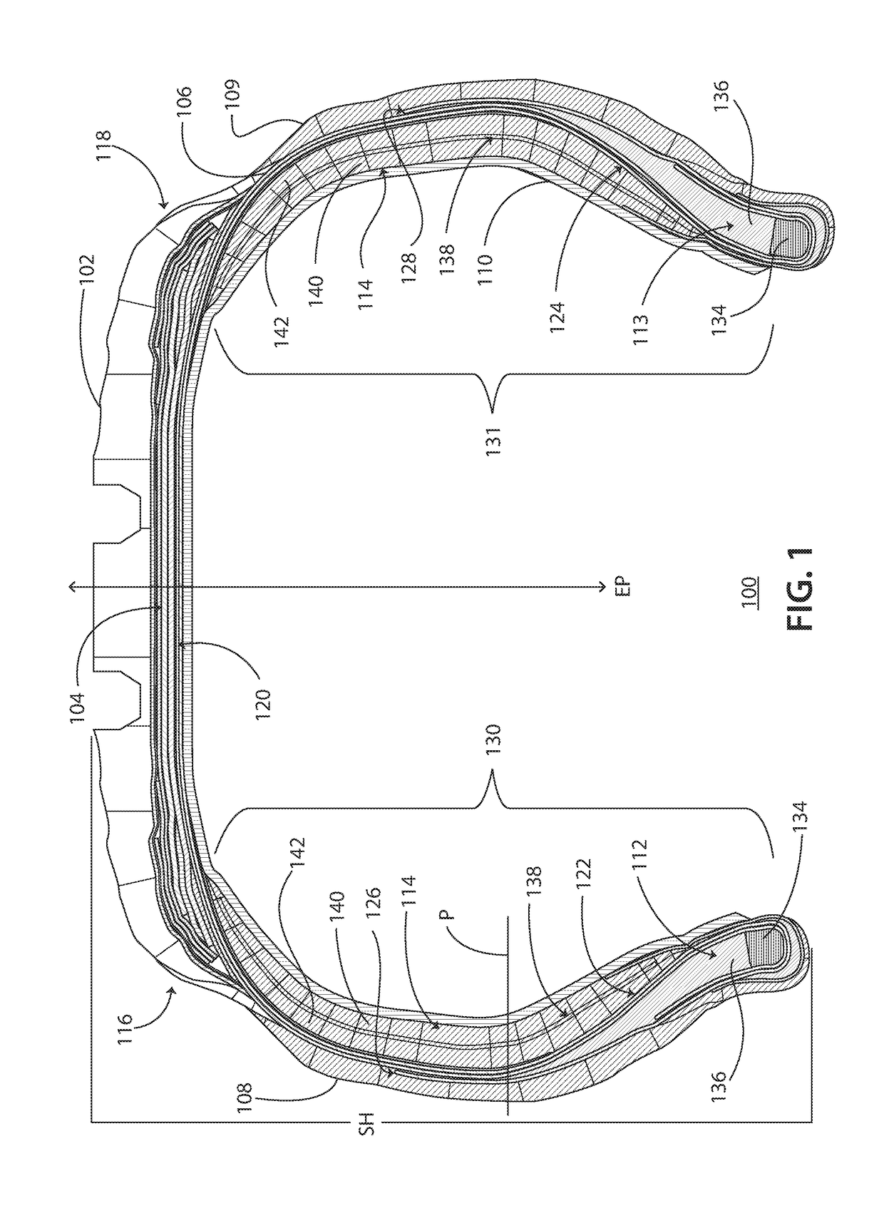
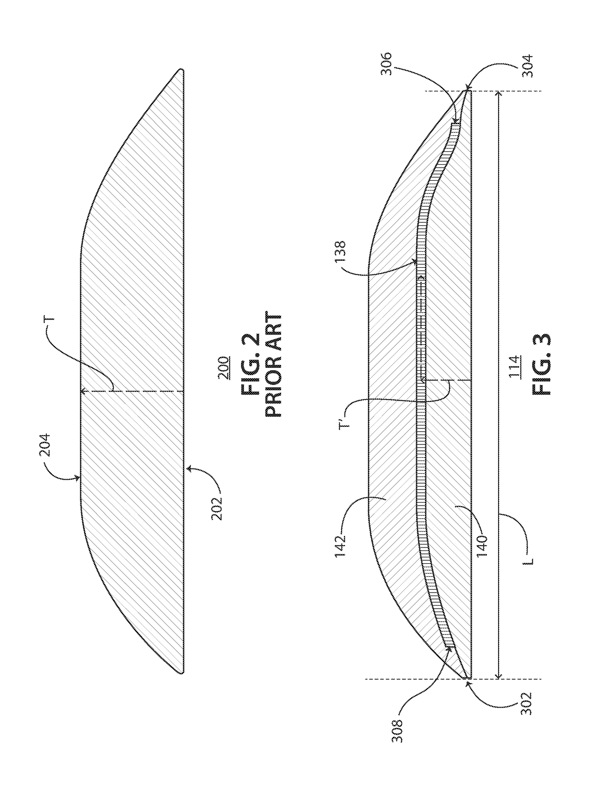
[0040]The present invention provides a novel and efficient run-flat tire with an improved sidewall-reinforcing insert that divides a standard-sized sidewall-reinforcing insert into two smaller, separate sidewall-reinforcing inserts with a fabric barrier interposed therebetween. The fabric barrier diverts a horizontal tear that normally travels through a thickness of the standard-sized insert from one surface to the opposing surface, so as to prolong the functional life of the run-flat tire in an uninflated or underinflated state. In ot...


PUM


Abstract

A run-flat tire having a tread, an inner liner disposed beneath the tread, a body ply, and a pair of sidewalls axially spaced apart from one another is disclosed. The run-flat tire further includes a pair of sidewall-reinforcing portions each disposed in respective sidewall regions and each having a fabric barrier; a first sidewall-reinforcing insert between the fabric barrier and the inner liner; and a second sidewall-reinforcing insert disposed between the fabric barrier and the body ply. The fabric barrier extends not more than an entire length of the sidewall-reinforcing portion.

Description

FIELD OF THE INVENTION[0001]The present invention relates generally to a run-flat tire and more particularly relates to a run-flat tire with sidewall-reinforcing inserts having a fabric barrier.BACKGROUND OF THE INVENTION[0002]It is well-known that automobile tires are provided in run-flat configurations. Run-flat tires are used by automobile manufacturers to eliminate the need for spare tires, thereby increasing available space within a vehicle and reducing vehicle curb weight. Many vehicle operators prefer the convenience of a run-flat tire because it is able to continue operating even under loss of inflation pressure. Run-flat tires are designed to be able to function for a limited time and distance at zero inflation pressure, also referred to in the art as a “zero (0) psi state.”[0003]Conventional run-flat tires may include a reinforced sidewall area to support a load in the zero psi state. Some conventional run-flat tires are supported in the zero psi state by a sidewall-reinfo...

Claims


Application Information

Patent Timeline
Patent Type & Authority Applications(United States)
IPC IPC(8): B60C17/00B60C9/12
CPCB60C17/0018B60C17/0036B60C9/12B60C17/00
Inventor KIRBY, JAMES M.
Owner BRIDGESTONE AMERICAS TIRE OPERATIONS LLC
Learn More