Cascoded circuit
a circuit and circuit technology, applied in the field of circuits, can solve the problems of enlarging the area of a pattern layout of an amplifier or a constant-current circuit, and having a small power supply voltage margin
- Summary
- Abstract
- Description
- Claims
- Application Information
AI Technical Summary
Problems solved by technology
Method used
Image

Examples
first embodiment
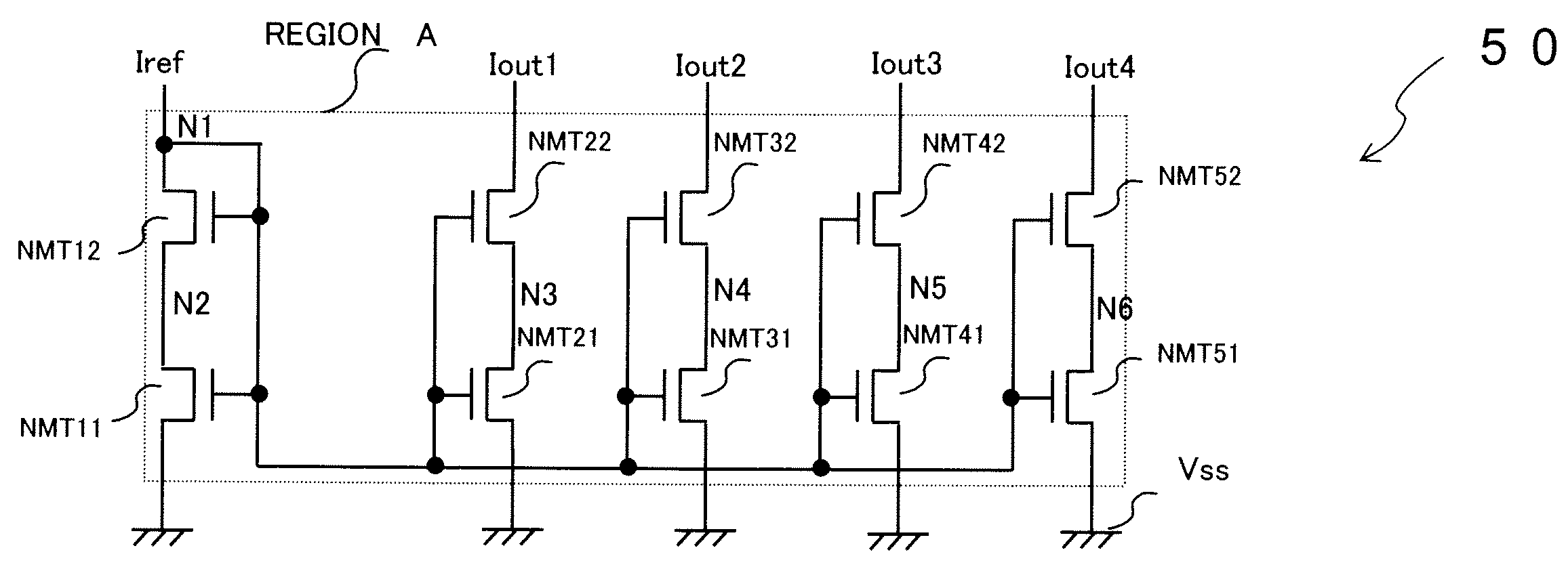
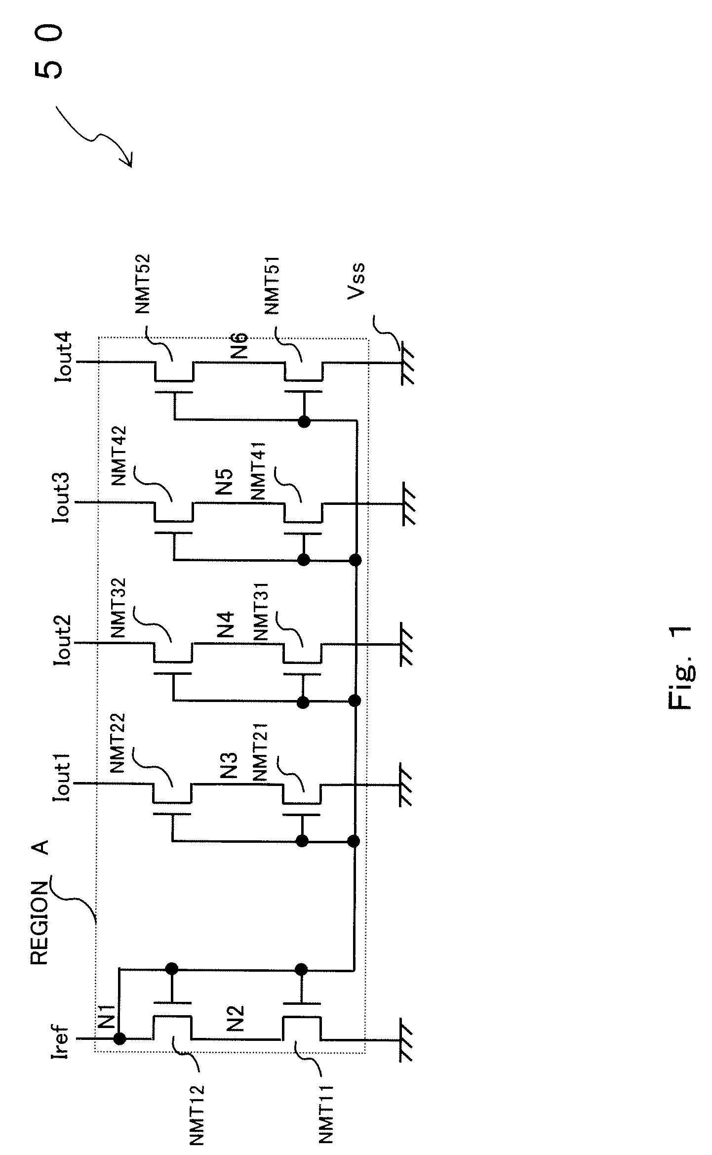
[0018]A cascoded circuit according to the present invention will be described referring to the drawings. FIG. 1 is a circuit diagram that shows a cascoded current-mirror circuit. In this embodiment, N channel MOS transistors that constitute a cascoded current-mirror circuit that operates in a linear region is formed in the same active region.
[0019]As shown in FIG. 1, a cascoded current-mirror circuit 50 includes an N channel MOS transistor NMT11, an N channel MOS transistor NMT12, an N channel MOS transistor NMT21, an N channel MOS transistor NMT22, an N channel MOS transistor NMT31, an N channel MOS transistor NMT32, an N channel MOS transistor NMT41, an N channel MOS transistor NMT42, an N channel MOS transistor NMT51 and an N channel MOS transistor NMT52.
[0020]The N channel MOS transistor NMT11, the N channel MOS transistor NMT12, the N channel MOS transistor NMT21, the N channel MOS transistor NMT22, the N channel MOS transistor NMT31, the N channel MOS transistor NMT32, the N c...
second embodiment
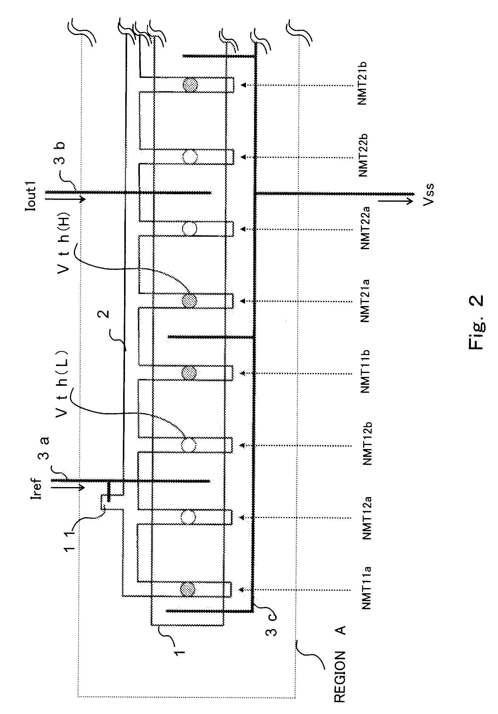
[0055]A cascoded circuit according to the present invention will be described referring to the drawings. FIG. 3 is a schematic plan view that shows a pattern layout of a cascoded current-mirror circuit. In this embodiment, N channel MOS transistors that constitute the cascoded current-mirror circuit that operates in a linear region are formed on the same active region, and the gate length dimensions of the N channel MOS transistors are changed.
[0056]As shown in FIG. 3, the N channel MOS transistor NMT11, the N channel MOS transistor NMT12, the N channel MOS transistor NMT21, the N channel MOS transistor NMT22, the N channel MOS transistor NMT31, the N channel MOS transistor NMT32, the N channel MOS transistor NMT41, the N channel MOS transistor NMT42, the N channel MOS transistor NMT51 and the N channel MOS transistor NMT52, that constitute a cascoded current-mirror circuit 50, are arranged and formed on the same active region 1. The gates of these transistors are arranged in parall...
third embodiment
[0073]A cascoded circuit according to the present invention will be described referring to the drawings. FIG. 4 is a circuit diagram that shows a cascoded current-mirror circuit. In this Embodiment, P channel MOS transistors that constitute a cascoded current-mirror circuit that operates in a linear region is formed in the same active region.
[0074]As shown in FIG. 4, a cascoded current-mirror circuit 51 includes a P channel MOS transistor PMT11, a P channel MOS transistor PMT12, a P channel MOS transistor PMT21, a P channel MOS transistor PMT22, a P channel MOS transistor PMT31, a P channel MOS transistor PMT32, a P channel MOS transistor PMT41, a P channel MOS transistor PMT42, a P channel MOS transistor PMT51 and a P channel MOS transistor PMT52.
[0075]Here, the P channel MOS transistor PMT11, the P channel MOS transistor PMT12, the P channel MOS transistor PMT21, the P channel MOS transistor PMT22, the P channel MOS transistor PMT31, the P channel MOS transistor PMT32, the P chann...
PUM
 Abstract
Description
Claims
Application Information
 - R&D Engineer
- R&D Manager
- IP Professional
- Industry Leading Data Capabilities
- Powerful AI technology
- Patent DNA Extraction
Browse by: Latest US Patents, China's latest patents, Technical Efficacy Thesaurus, Application Domain, Technology Topic.
© 2024 PatSnap. All rights reserved.Legal|Privacy policy|Modern Slavery Act Transparency Statement|Sitemap