
Laser light source and method of operating the same

a laser light source and laser light technology, applied in the direction of laser details, optical resonator shape and construction, electrical apparatus, etc., can solve the problems of reducing the power output of the optical fiber amplifier by up to 90%, unsatisfactory nonlinear optical effects, and reducing the likelihood of stimulating brillouin scattering and/or other nonlinear effects, etc., to achieve the effect of reducing the probability of nonlinear effects, reducing the spectral density, and reducing the likelihood o

Active Publication Date: 2009-04-16
II VI DELAWARE INC
View PDF7 Cites 14 Cited by
  • Summary
  • Abstract
  • Description
  • Claims
  • Application Information

AI Technical Summary

Benefits of technology

The invention reduces or limits the amount of laser light that can cause damage by reducing the chances of stimulatedBrillouin scattering (SRS) and other nonlinear effects from happening. This means that more efficient use of lasers can be made without causing harmful side effects.

Problems solved by technology

The technical problem addressed in this patent text relates to reducing or eliminating nonlinear optical effects like stimulatedBrillouin scattering in laser systems caused by high spectral power density. These effects can lead to decreased power output and damaged equipment.

Method used


Image

  • Laser light source and method of operating the same
  • Laser light source and method of operating the same
  • Laser light source and method of operating the same

Examples


Embodiment Construction

[0023]While the present subject matter is described with reference to the embodiments as illustrated in the following detailed description as well as in the drawings, it should be understood that the following detailed description as well as the drawings are not intended to limit the present invention to the particular embodiments disclosed, but rather the described embodiments merely exemplify the various aspects of the present subject matter, the scope of which is defined by the appended claims.

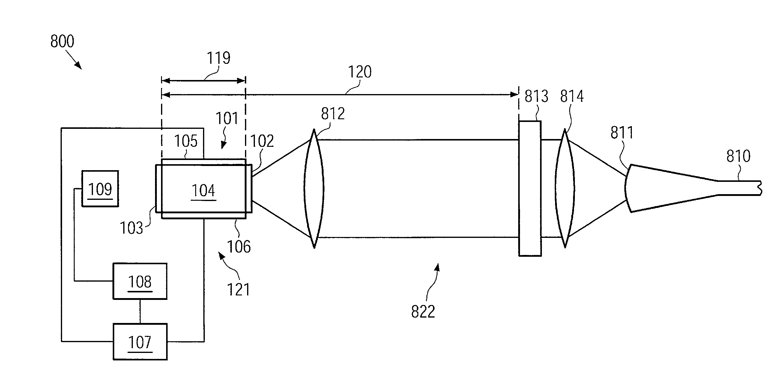
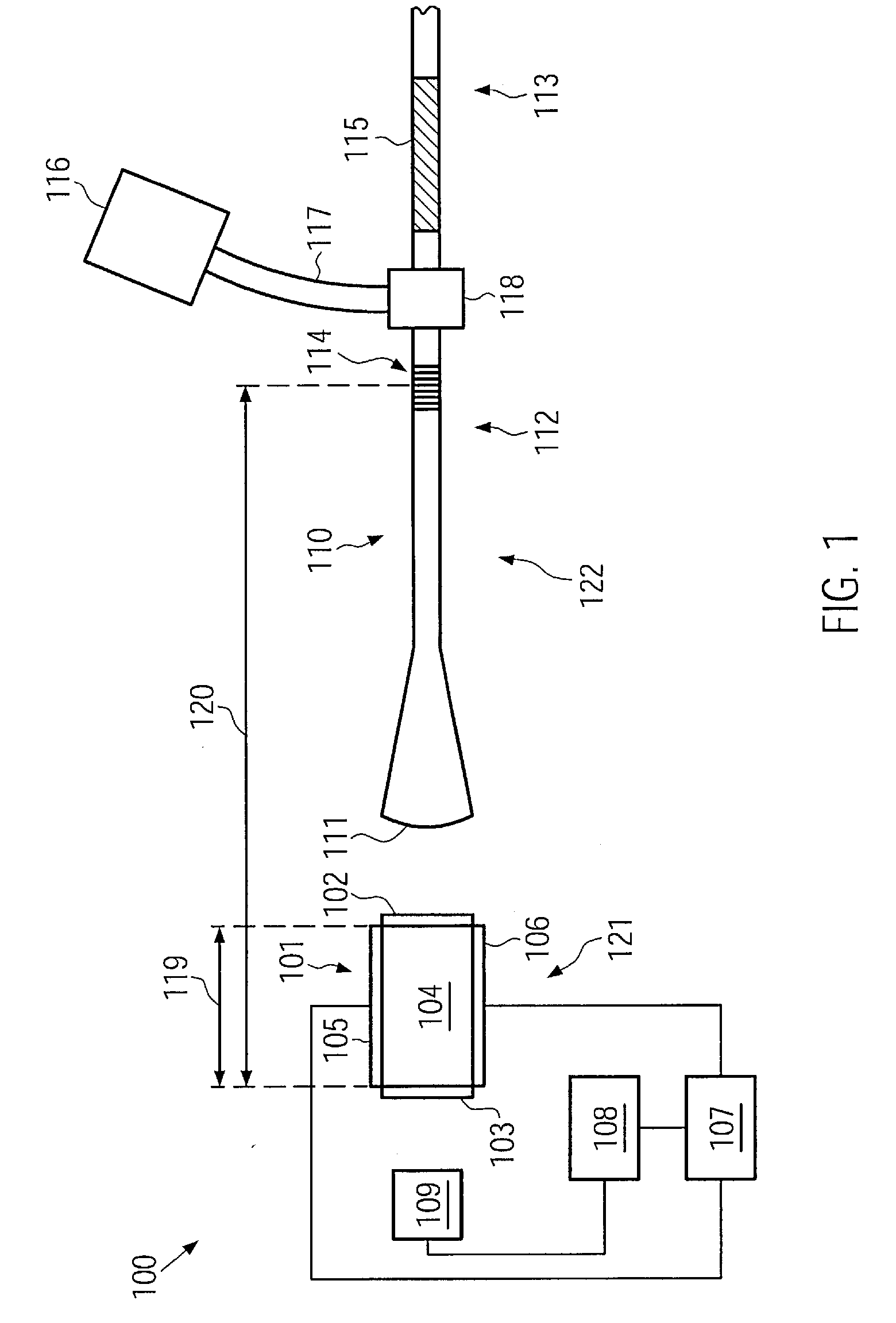
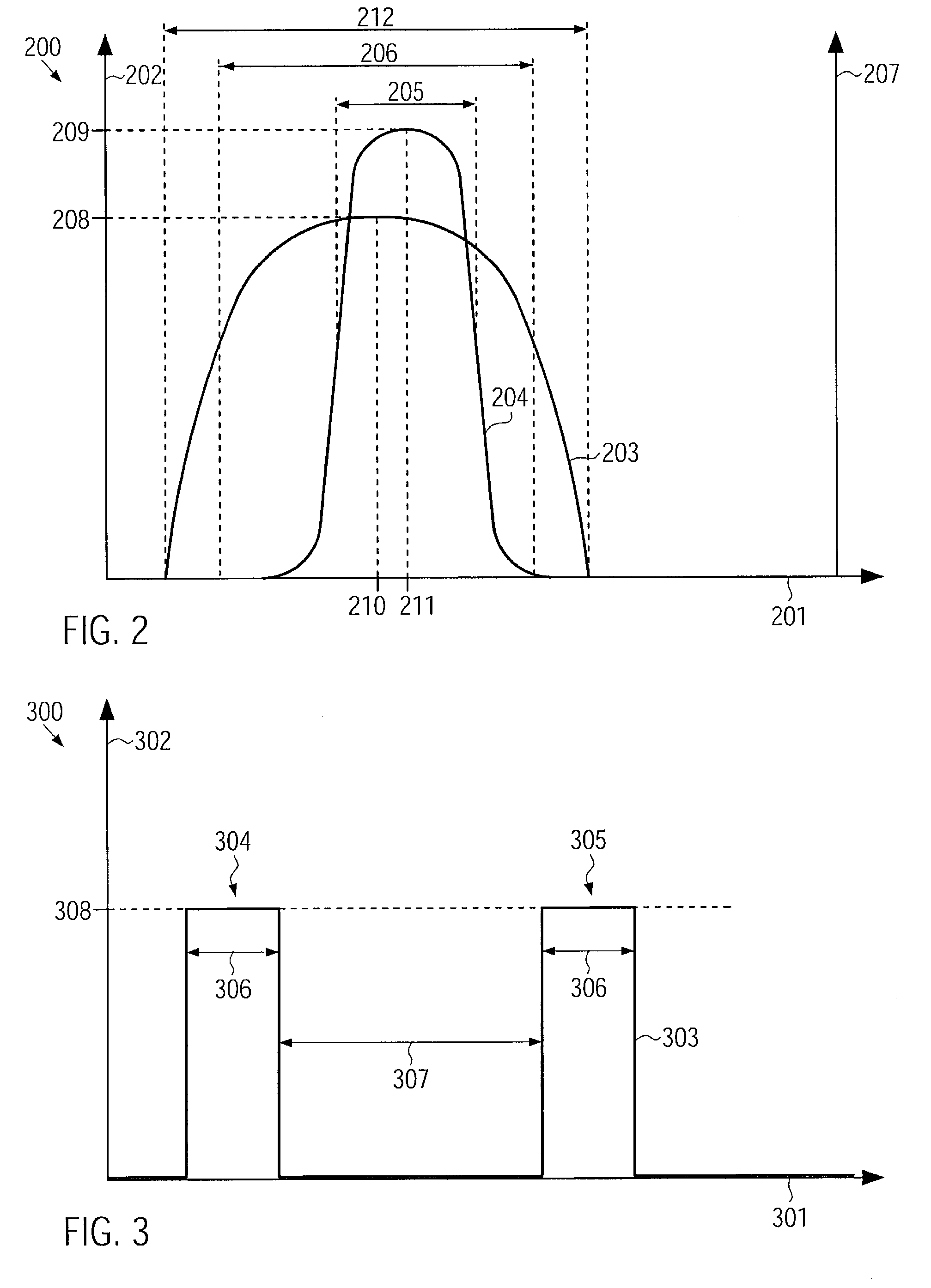
[0024]According to one embodiment, a laser light source comprises a semiconductor laser adapted for pulsed operation. For pulsed operation of the semiconductor laser, a pulsed electric current may be supplied to the semiconductor laser. An output power of the semiconductor laser during the pulses may, in some embodiments, be relatively high. Thus, the optical fiber amplifier may be driven without a pre-amplification stage, or a number of pre-amplification stages used may be reduced.

[0025]In...


PUM


Abstract

A laser light source comprises a semiconductor laser adapted for pulsed operation, a partially transmitting wavelength selective light reflector. The semiconductor laser comprises a front facet and a back facet. The front facet and the back facet define an internal laser cavity. The internal laser cavity comprises a laser active medium. The partially transmitting wavelength selective light reflector has a peak reflectivity within a gain bandwidth of said laser active medium. The wavelength selective light reflector and the back facet define an external laser cavity. A roundtrip time of light in the external laser cavity is about 20 nanoseconds or less. A full width half maximum bandwidth of the wavelength selective light reflector is adapted to accommodate at least 12 longitudinal modes of the internal laser cavity and at least 250 longitudinal modes of the external laser cavity.

Description


Claims


Application Information

Patent Timeline
Owner II VI DELAWARE INC
Learn More