
Apparatus and method for generating a bandwidth extended signal

a bandwidth extended and signal technology, applied in the field of apparatus and methods for generating bandwidth extended signals, can solve the problems of reducing subjective audio quality, high computational effort of filterbank computation and patching in the filterbank domain, etc., and achieve the effects of significantly improving extending the bandwidth of an input signal, and significantly increasing the audio quality of the bandwidth extended signal

Active Publication Date: 2014-11-04
FRAUNHOFER GESELLSCHAFT ZUR FOERDERUNG DER ANGEWANDTEN FORSCHUNG EV
View PDF27 Cites 1 Cited by
  • Summary
  • Abstract
  • Description
  • Claims
  • Application Information

AI Technical Summary

Benefits of technology

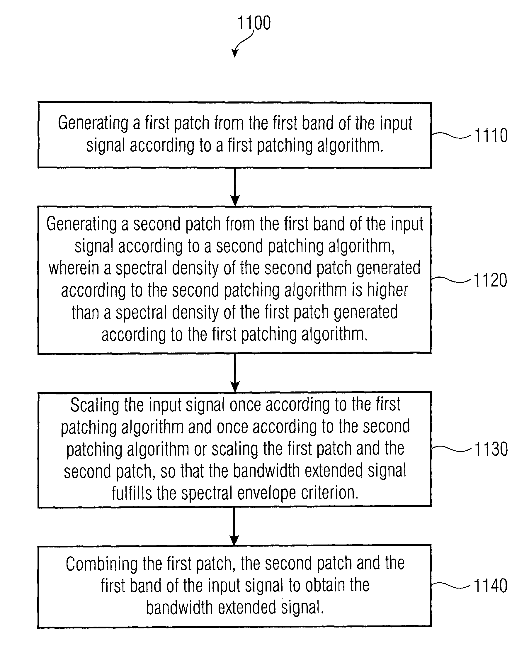
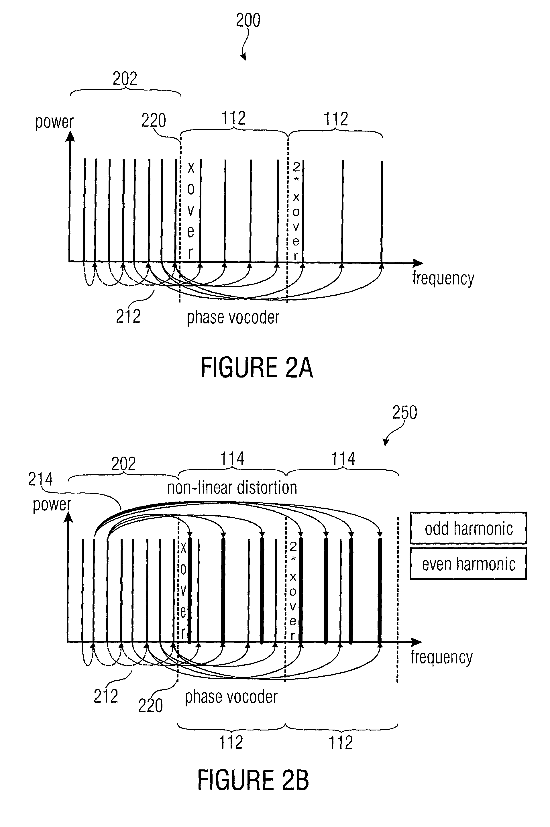
The present invention relates to a method for extending the bandwidth of an audio signal by combining two patches with different spectral densities. The first patch has low spectral density, meaning it contains many gaps, and the second patch has high spectral density, meaning it has fewer gaps. By combining the two patches, the high frequency bandwidth of the audio signal can be approximated, resulting in a better quality audio signal. The method also involves scaling the input signal before or after generation to meet a spectral envelope criterion, which improves the subjective quality or audio quality of the bandwidth extended signal. Further, a harmonic patching algorithm is used to generate the first patch with low spectral density, and a mixing patching algorithm is used to generate the second patch with high spectral density. This helps fill the gaps in the harmonic bandwidth extension and improves the overall audio quality.

Problems solved by technology

However, the coding used for this, in particular when operating at lowest bit rates, can lead to an reduction of subjective audio quality which is often mainly caused by an encoder side induced limitation of the audio signal bandwidth to be transmitted.
In particular, filterbank calculations and patching in the filterbank domain may become a high computational effort.

Method used


Image

  • Apparatus and method for generating a bandwidth extended signal
  • Apparatus and method for generating a bandwidth extended signal
  • Apparatus and method for generating a bandwidth extended signal

Examples


Embodiment Construction

[0044]In the following, the same reference numerals are partly used for objects and functional units having the same or similar functional properties and the description thereof with regard to a figure shall apply also to other figures in order to reduce redundancy in the description of the embodiments.

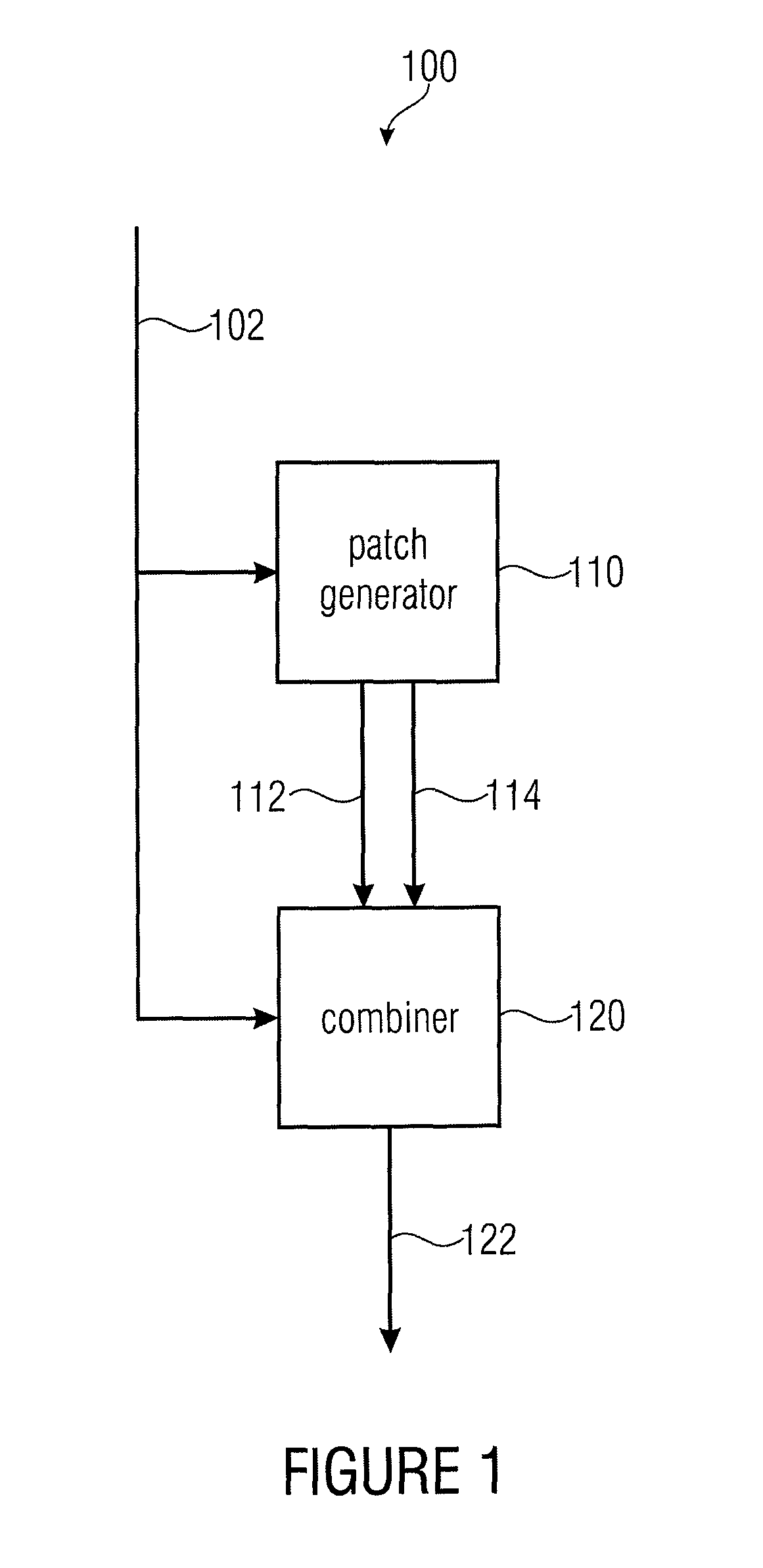
[0045]FIG. 1 shows a block diagram of an apparatus 100 for generating a bandwidth extended signal 122 for an input signal 102 according to an embodiment of the invention. The input signal 102 is represented, for a first band by a first resolution data, and for a second band by a second resolution data, the second resolution being lower than the first resolution. The apparatus 100 comprises a patch generator 110 connected to a combiner 120. The patch generator 120 generates a first patch 112 from the first band of the input signal 102 according to a first patching algorithm and generates a second patch 114 from the first band of the input signal 102 according to a second patching algor...


PUM


Abstract

An apparatus for generating a bandwidth extended signal from an input signal includes a patch generator and a combiner. The input signal is represented for first and second bands by first and second resolution data, respectively, the second resolution being lower than the first. The patch generator generates first and second patches from the first band of the input signal according to first and second patching algorithms, respectively. A spectral density of the second patch generated using the second patching algorithm is higher than a spectral density of a first patch generated using the first patching algorithm. The combiner combines both patches and the first band of the input signal to obtain the bandwidth extended signal. The apparatus scales the input signal according to the first and second patching algorithms or scales the first and second patches, so that the bandwidth extended signal fulfills a spectral envelope criterion.

Description

CROSS-REFERENCE TO RELATED APPLICATIONS[0001]This application is a continuation of copending International Application No. PCT / EP2009 / 004603 filed Jun. 25, 2009, and also claims priority to U.S. Application No. 61 / 079,849, filed Jul. 11, 2008, which is incorporated herein by reference in its entirety.[0002]Embodiments according to the invention relate to audio signal processing and, in particular, to an apparatus and a method for generating a bandwidth extended signal from an input signal, an apparatus and a method for providing a bandwidth reduced signal based on an input signal and an audio signal.BACKGROUND OF THE INVENTION[0003]Perceptually adapted coding of audio signals, providing a substantial data rate reduction for efficient storage and transmission of these signals, has gained wide acceptance in many fields. Many coding algorithms are known, e.g., MPEG 1 / 2 Layer 3 (“MP3”) or MPEG 4 AAC (Advanced Audio Coding). However, the coding used for this, in particular when operating...

Claims


Application Information

Patent Timeline
Patent Type & Authority Patents(United States)
IPC IPC(8): G10L19/00G10L21/038
CPCG10L21/038
Inventor NAGEL, FREDERIKDISCH, SASCHANEUENDORF, MAXBAYER, STEFANGAYER, MARCLOHWASSER, MARKUSRETTELBACH, NIKOLAUSKRAEMER, ULRICH
Owner FRAUNHOFER GESELLSCHAFT ZUR FOERDERUNG DER ANGEWANDTEN FORSCHUNG EV
Learn More