Laser light source and method of operating the same

a laser light source and laser light technology, applied in the direction of laser details, optical resonator shape and construction, electrical apparatus, etc., can solve the problems of reducing the power output of the optical fiber amplifier by up to 90%, unsatisfactory nonlinear optical effects, and reducing the likelihood of stimulating brillouin scattering and/or other nonlinear effects, etc., to achieve the effect of reducing the probability of nonlinear effects, reducing the spectral density, and reducing the likelihood o

Active Publication Date: 2012-06-12
II VI DELAWARE INC
View PDF10 Cites 0 Cited by
  • Summary
  • Abstract
  • Description
  • Claims
  • Application Information

AI Technical Summary

Benefits of technology

[0013]Contrary thereto, laser light sources and methods according to the present subject matter allow to reduce the spectral density within the stimulated Brillouin scattering gain bandwidth and / or may limit a duration of periods of time wherein relatively high spectral densities occur to less than the build-up time of stimulated Brillouin scattering. Thus, the likelihood of stimulated Brillouin scattering and / or other nonlinear effects occurring may be reduced.

Problems solved by technology

A problem of seeded optical fiber amplifiers according to the state of the art is that, with high spectral power densities, undesirable nonlinear optical effects such as stimulated Brillouin scattering may be created in the optical fiber amplifier and / or in other optical fibers provided in the laser radiation source or connected thereto.
This may reduce the power output of the optical fiber amplifier by up to 90% and / or can cause severe damage to amplifier components, including semiconductor seed and pump lasers.

Method used


Image

  • Laser light source and method of operating the same
  • Laser light source and method of operating the same
  • Laser light source and method of operating the same

Examples


Embodiment Construction

[0023]While the present subject matter is described with reference to the embodiments as illustrated in the following detailed description as well as in the drawings, it should be understood that the following detailed description as well as the drawings are not intended to limit the present invention to the particular embodiments disclosed, but rather the described embodiments merely exemplify the various aspects of the present subject matter, the scope of which is defined by the appended claims.

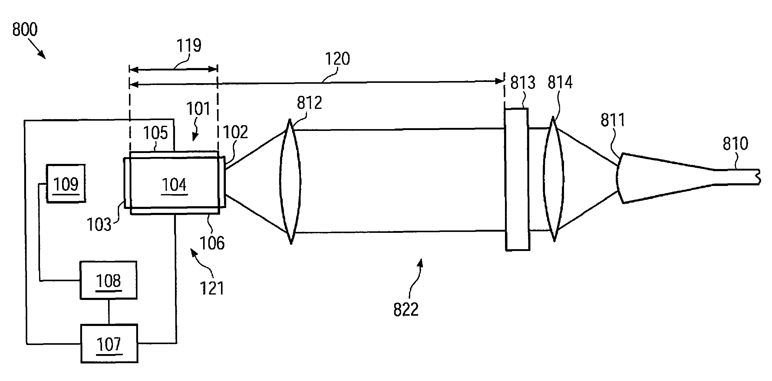
[0024]According to one embodiment, a laser light source comprises a semiconductor laser adapted for pulsed operation. For pulsed operation of the semiconductor laser, a pulsed electric current may be supplied to the semiconductor laser. An output power of the semiconductor laser during the pulses may, in some embodiments, be relatively high. Thus, the optical fiber amplifier may be driven without a pre-amplification stage, or a number of pre-amplification stages used may be reduced.

[0025]In...


PUM


Abstract

A laser light source comprises a semiconductor laser adapted for pulsed operation, a partially transmitting wavelength selective light reflector. The semiconductor laser comprises a front facet and a back facet. The front facet and the back facet define an internal laser cavity. The internal laser cavity comprises a laser active medium. The partially transmitting wavelength selective light reflector has a peak reflectivity within a gain bandwidth of said laser active medium. The wavelength selective light reflector and the back facet define an external laser cavity. A roundtrip time of light in the external laser cavity is about 20 nanoseconds or less. A full width half maximum bandwidth of the wavelength selective light reflector is adapted to accommodate at least 12 longitudinal modes of the internal laser cavity and at least 250 longitudinal modes of the external laser cavity.

Description

[0001]This application claims priority under 35 USC §119(e) to U.S. Provisional Application No. 60 / 979,985, filed Oct. 15, 2007. The entire disclosure of the application is hereby incorporated herein by reference.FIELD OF THE PRESENT INVENTION[0002]The present invention generally relates to laser light sources, more particular to laser light sources comprising a semiconductor laser and / or an optical fiber amplifier, and to laser light sources which may be used in laser machining processes such as laser welding, laser ablation, laser annealing, laser sintering, laser printing, laser scribing, laser marking, laser drilling and / or laser patterning, as well as in medical applications, for example in surgery and diagnostic imaging.DESCRIPTION OF THE RELATED ART[0003]In modern manufacturing technology, laser machining processes such as laser marking, laser welding, and laser cutting play an important role. In these applications, laser radiation generated by a laser light source is made to...

Claims


Application Information

Patent Timeline
Patent Type & Authority Patents(United States)
IPC IPC(8): H01S3/098H01S3/13
CPCH01S5/146H01S3/06754H01S3/094003H01S3/09415H01S3/1305H01S5/06216H01S5/0657H01S2301/03H01S5/1021H01S5/141H01S2301/06H01S3/094076H01S5/0287H01S5/06835
Inventor MOHRDIEK, STEFANTROGER, JOERGMATUSCHEK, NICOLAI
Owner II VI DELAWARE INC
Why Eureka
Try Eureka