Backlight device and display device

a backlight device and display device technology, applied in the direction of illuminated signs, display means, instruments, etc., can solve the problems of difficult uniformity, non-uniformity of brightness on light emitting surfaces, and difficulty in achieving uniform brightness. achieve the effect of uniform brightness

Inactive Publication Date: 2009-04-23
SHARP KK
View PDF5 Cites 33 Cited by
  • Summary
  • Abstract
  • Description
  • Claims
  • Application Information

AI Technical Summary

Benefits of technology

[0010]In the light of the problems described above, preferred embodiments of the present invention provide a backlight device and a display device that can make uniform the brightness on a light emitting surface, even when using a longitudinal lamp.

Problems solved by technology

However, the above-described conventional backlight device may cause problems in that non-uniformity of the brightness is generated on the light emitting surface and the brightness on the light emitting surface is difficult to be made uniform.
As a result, in the longitudinal direction of each lamp, a difference between the brightness of the high voltage side and the brightness of the low voltage side is increased, whereby the non-uniformity of the brightness appears on the light emitting surface.
In particular, according to the increase of the screen size of the liquid crystal display, when using a longitudinal lamp with an extended dimension in the longitudinal direction, the conventional backlight device cannot suppress an influence of the non-uniformity of the brightness due to the brightness inclination in each lamp to appear significantly on the light emitting surface, and it was difficult to make uniform the brightness on the light emitting surface.

Method used


Image

  • Backlight device and display device
  • Backlight device and display device
  • Backlight device and display device

Examples


first preferred embodiment

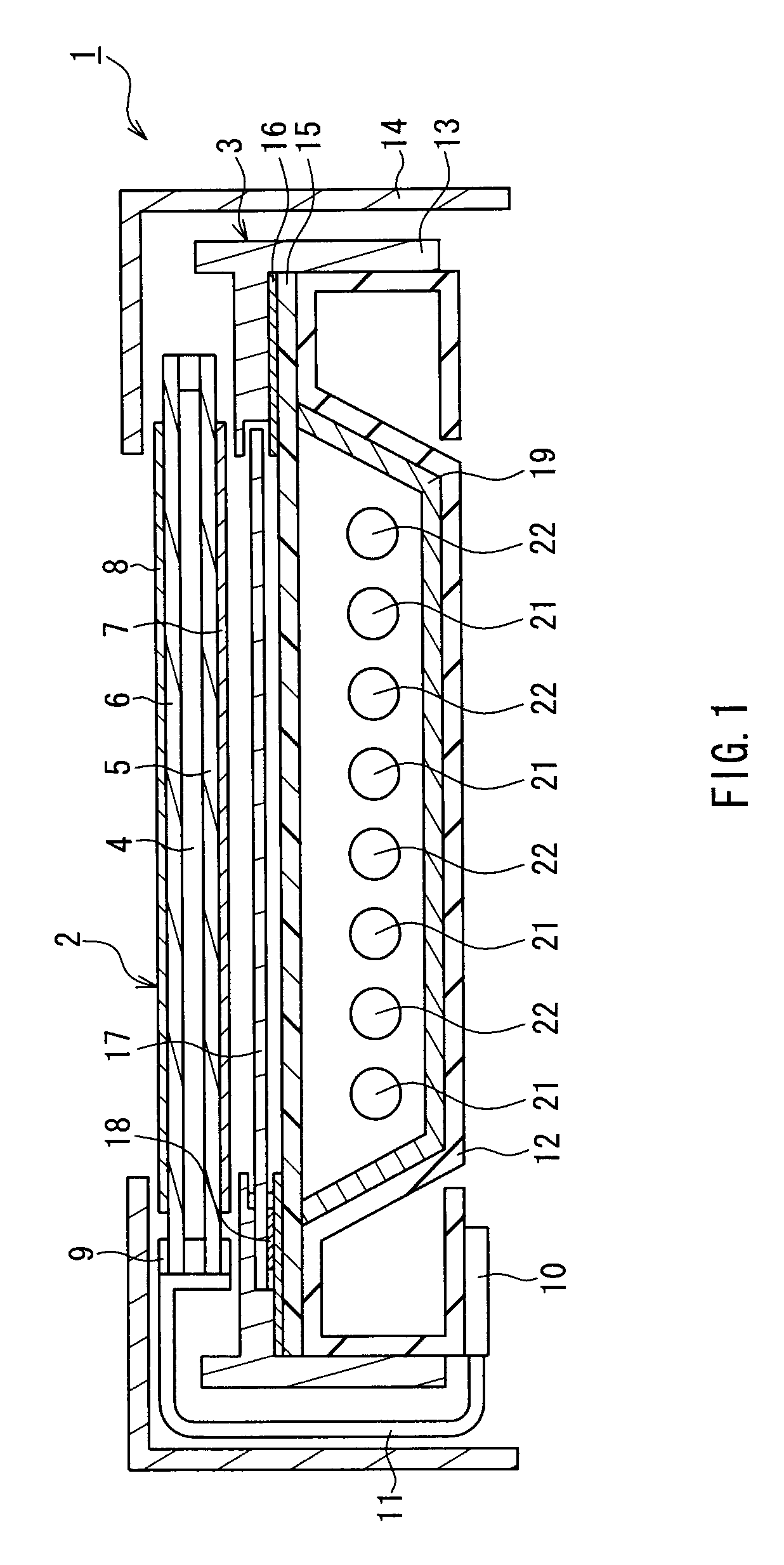
[0034]FIG. 1 is a schematic cross-sectional view illustrating a backlight device and a liquid crystal display device according to a first preferred embodiment of the present invention. In the figure, the liquid crystal display device 1 of the present preferred embodiment is provided with a liquid crystal panel 2 as a display portion, which is disposed so that its visible side (display surface side) is the upper side in the figure, and a backlight device 3 of the present preferred embodiment that is disposed on a non-display surface side of the liquid crystal panel 2 (the lower side of the figure) and generates illumination light for illuminating the liquid crystal panel 2.

[0035]The liquid crystal panel 2 is provided with a liquid crystal layer 4, a pair of transparent substrates 5 and 6 that sandwich the liquid crystal layer 4, and polarizing plates 7 and 8 that are provided on outer surfaces of the transparent substrates 5 and 6, respectively. Moreover, the liquid crystal panel 2 i...

second preferred embodiment

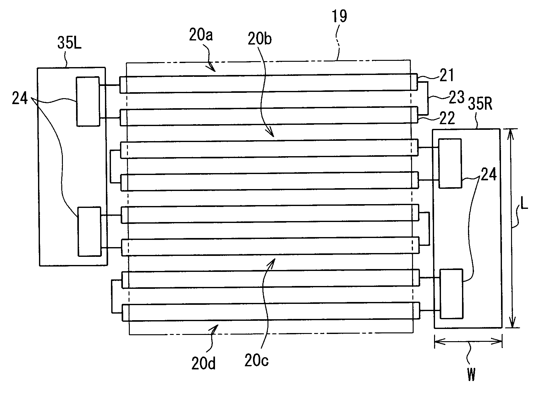
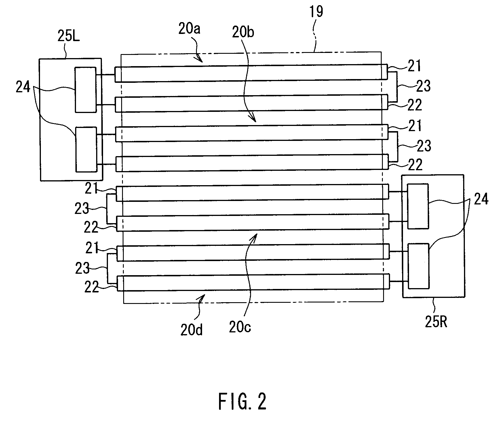
[0052]FIG. 4 is a plan view showing an arrangement of lamp units in the backlight device according to a second preferred embodiment of the present invention. In the figure, a main difference between the present preferred embodiment and the first preferred embodiment described above lies in that a plurality of inverter circuits are disposed alternately on one end portion side and other end portion side of the longitudinal direction, in the direction perpendicular to the longitudinal direction of the cold cathode-ray tube. Incidentally, the elements that are common with those in the first preferred embodiment are denoted by the same reference numbers, and the explanations thereof will be omitted.

[0053]As shown in FIG. 4, in the present preferred embodiment, on a substrate 35L on a left end portion side of the figure, the inverter circuits 24 of the lamp units 20a and 20c are disposed. Moreover, on the substrate 35R on a right end portion side of FIG. 4, the inverter circuits 24 of the...


PUM


Abstract

In a backlight device, lamp units including cold cathode-ray tubes (straight-tube lamp portions) and inverter circuits (driving circuits) for driving to switch on the cold cathode-ray tubes are arranged along a direction that is substantial perpendicular to a longitudinal direction of the cold cathode-ray tubes. Further, the inverter circuits of the lamp units are disposed separately on one end portion side and other end portion side in the longitudinal direction of the cold cathode-ray tubes. Thereby, even when using the longitudinal cold cathode-ray tubes, brightness on a light emitting surface can be made uniform.

Description

BACKGROUND OF THE INVENTION[0001]1. Field of the Invention[0002]The present invention relates to a backlight device having a plurality of straight-tube lamps (linear light sources) and a display device using the same.[0003]2. Description of the Related Art[0004]Recently, for example, liquid crystal display devices have been used widely for liquid crystal television sets, monitors, mobile phones and the like, as flat panel displays having features of small thickness, light weight and the like, compared with conventional Braun tubes. Such a liquid crystal display includes an illumination device (backlight device) that emits light and a liquid crystal panel that displays desired images by functioning as a shutter with respect to the light from a light source provided in the backlight device.[0005]Moreover, the backlight devices are classified into direct types and edge-light types according to the arrangement of the light source with respect to the liquid crystal panel. For the liquid ...

Claims


Application Information

Patent Timeline
Patent Type & Authority Applications(United States)
IPC IPC(8): F21V19/00
CPCG02F1/133604G02F2001/133612G02F1/133611G02F1/133608G02F1/133612
Inventor KOH, HIDEKI
Owner SHARP KK
Why Eureka
Try Eureka