
System and method for developing and deploying sensor and actuator applications over distributed computing infrastructure

a distributed computing and actuator technology, applied in the field of sensor and actuator systems, can solve the problems of complex conventional application logic employed, unintegrated application development and execution environment, and complex application logi

Inactive Publication Date: 2009-04-23
IBM CORP
View PDF0 Cites 39 Cited by
  • Summary
  • Abstract
  • Description
  • Claims
  • Application Information

AI Technical Summary

Benefits of technology

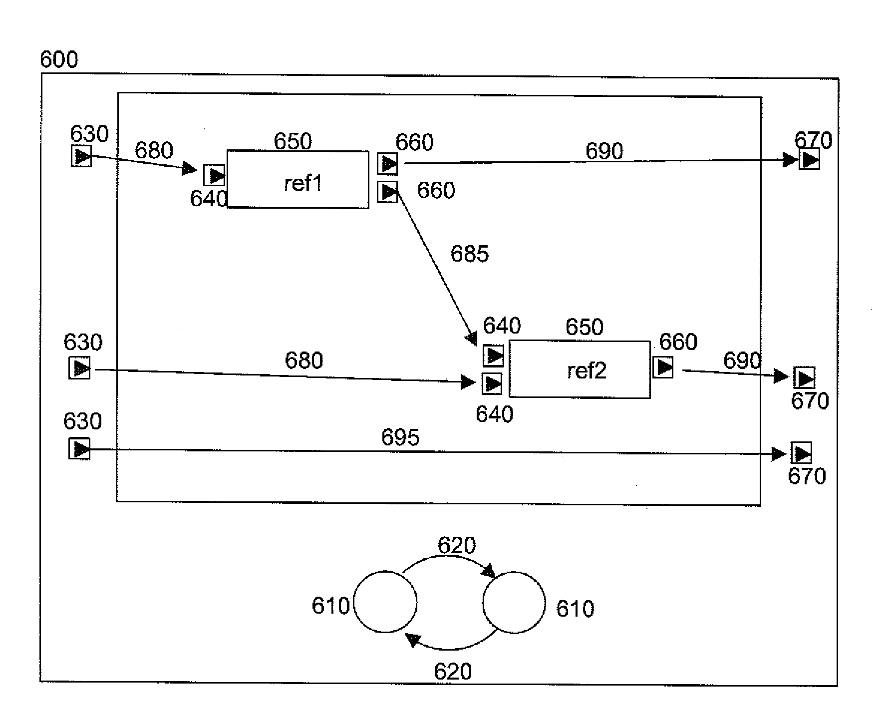
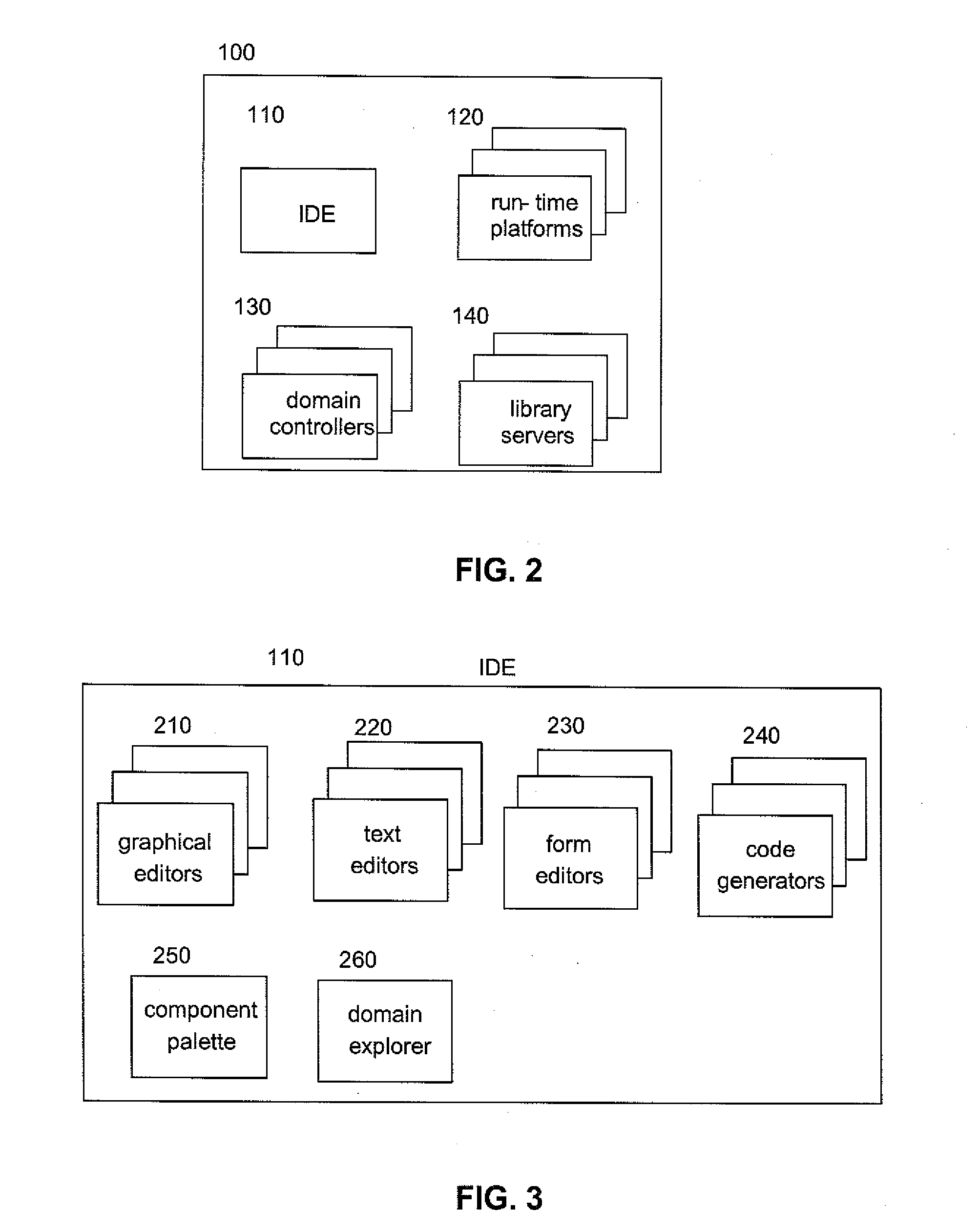
[0033]In yet a further aspect of the invention, the tool units includes one or more domain controllers to administer the run-time platforms.
[003

Problems solved by technology

However, conventional business and industrial operations do not provide an integrated application development and execution environment, which addresses the challenges regarding life-cycle support of applications employing sensors or actuators.
Another challenge in providing integrated application development and execution environment is interconnecting sensors and actuators with the Internet, where sensors and actuators act as interfaces between the physical world and cyberspace.
Some other challenges in providing integrated application development and execution environment relate to the complexity of the conventional application logic employed in a typical sensor / actuator application.
Their conundrum is compounded by the potentially diverse, distributed computing platforms on which the application may execute.
The lack of a unified programming model and tooling support results in a steep learning curve and integration complexity for sensor / actuator application development.

Method used


Image

  • System and method for developing and deploying sensor and actuator applications over distributed computing infrastructure
  • System and method for developing and deploying sensor and actuator applications over distributed computing infrastructure
  • System and method for developing and deploying sensor and actuator applications over distributed computing infrastructure

Examples


Embodiment Construction

[0047]The present invention has two aspects. The first aspect is a method of modeling, implementing, and deploying computer systems, including but not limited to computer systems involving sensors, actuators, or both. The second aspect is a system providing assistance to designers, implementers, and deplorers of computer systems, including but not limited to computer systems involving sensors, actuators, or both.

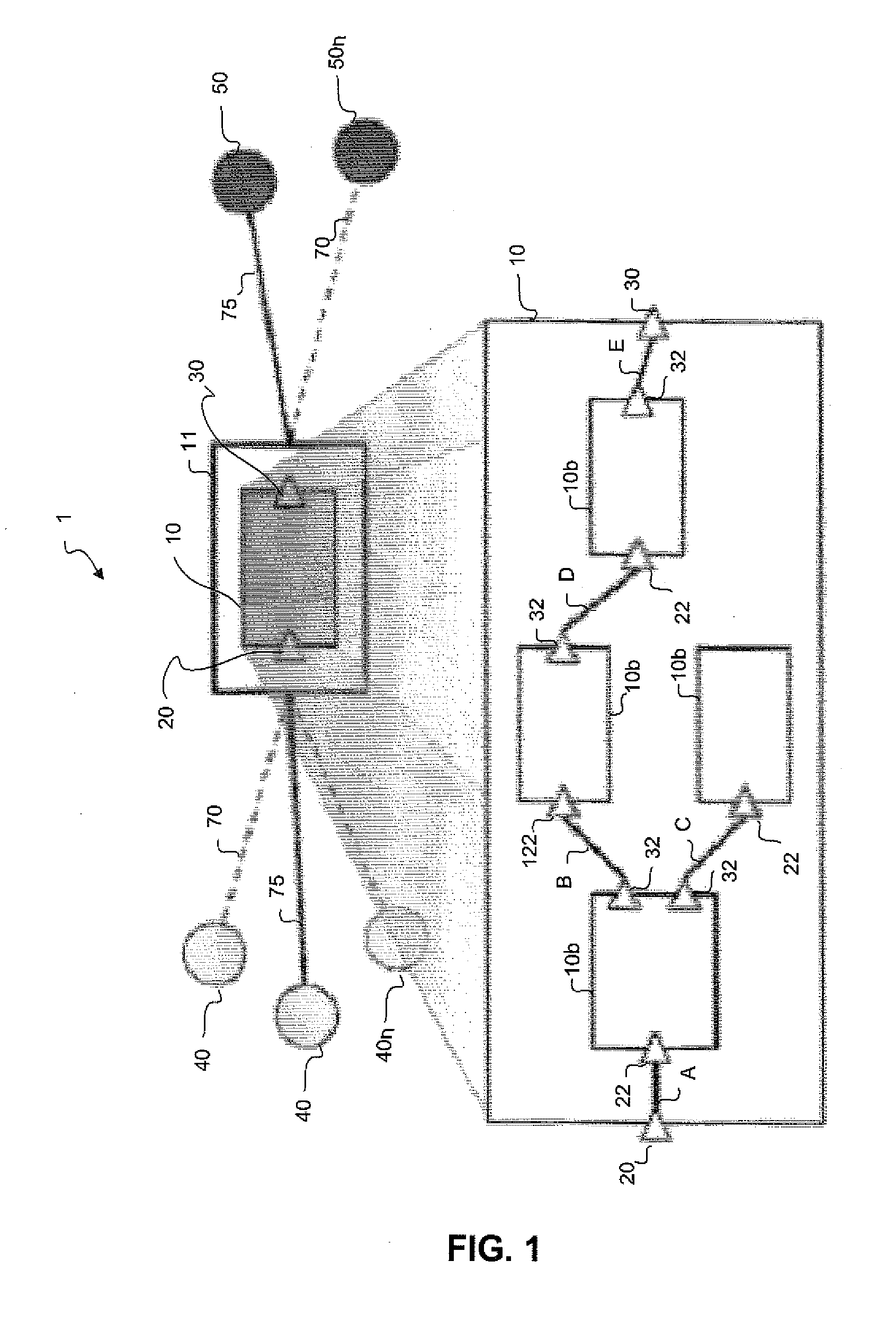
[0048]Sensors and actuators can be leveraged and used to trigger the business processes and scenarios as described in the background of invention section, where in order to carry out functions desired by users, sensors and actuator devices are coordinated. For example as can be seen in FIG. 1, an integrated embedded device solution 1 accomplishes this by connecting sensors 40 / 40n and actuators 50 / 50n devices to a controller node 11 and a composite component 10 via wireless links 70 or wired links 75 and input port 20 and output port 30. Within the controller node 11, the com...


PUM


Abstract

The present invention discloses a method for coordinating zero or more modelings, zero or more implementations and zero or more deployments of a computer system, including but not limited to computer systems involving sensors, actuators, or both and a system providing assistance to designers, implementers, and deployers of computer systems. The method and system including: defining one or more interfaces of one or more components; creating models for the one or more components, each of which is either a composite component model or a atomic component, model, creating the one or more composite components as instances of the composite component models creating the one or more atomic components as instances of the atomic component models creating a domain model by specifying the computational resources; and creating a deployment model by specifying one or more component-model instances and specifying which the component-model instances should be executed on which the computational resources of the domain model.

Description

BACKGROUND OF THE INVENTION[0001]1. Field of the Invention[0002]The present invention relates to sensor and actuator systems for monitoring and controlling processes generally, and particularly to a system and method of modeling, implementing and deploying computer systems for sensor and actuators.[0003]2. Discussion of the Prior Art[0004]Sensors and actuators have long played a critical role for industry applications. For example, a manufacturing process-control program might use temperature, pressure and acidity sensors to determine the current state of a chemical or metallurgical process, and actuators such as valves, heaters, and coolers to control that process. In another example, an automated assembly line might deploy photo sensors and tactile-pressure sensors to guide robotic actuators to execute manufacturing operations. Such applications are typically self-contained as they are optimized to enable their specific operations.[0005]More recently, with the advent of RFID (Radi...

Claims


Application Information

Patent Timeline
IPC IPC(8): G06G7/62
CPCG06F8/10G06F9/448G06F9/4494G06F30/15
Inventor CHEN, HANCHOU, PAUL B.COHEN, NORMAN H.DURI, SASTRY S.EOM, YONGHUNJUNG, CHANGWOOKIM, SOOYEONREASON, JOHNATHAN M.WONG, DANNY CHAN-YONG
Owner IBM CORP
Learn More