AI technical title is built by PatSnap AI team. It summarizes the technical point description of the patent document.
a diagnostic system and diagnostic data technology, applied in the field of system maintenance and diagnosis, can solve the problems of cumbersome sending such a large volume of data to the diagnosis site, consuming a lot of time and valuable system resources, and reducing the time needed
Active Publication Date: 2009-04-23
ORACLE INT CORP
View PDF35 Cites 70 Cited by
Summary
Abstract
Description
Claims
Application Information
AI Technical Summary
This helps you quickly interpret patents by identifying the three key elements:
Problems solved by technology
Method used
Benefits of technology
Benefits of technology
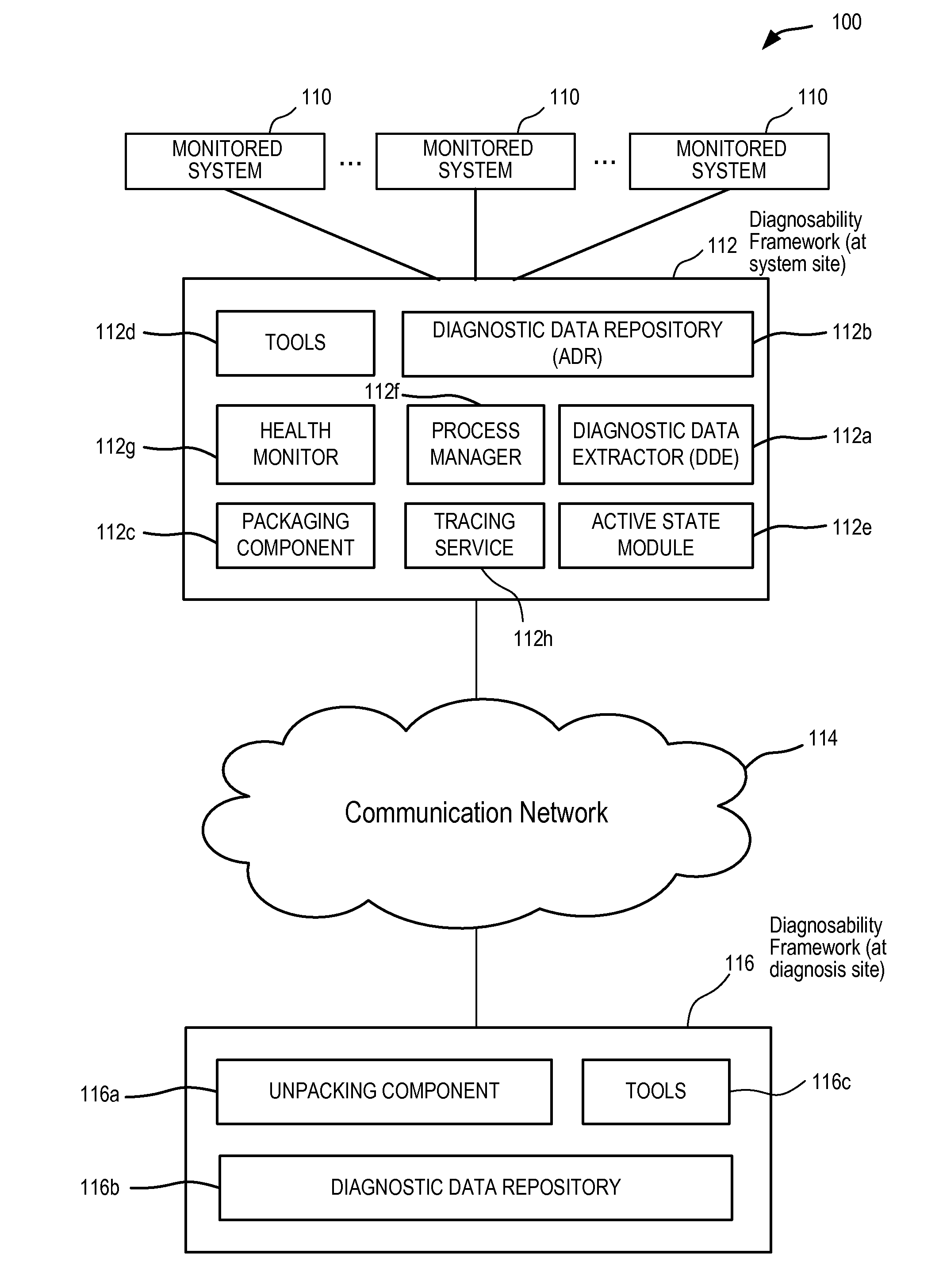
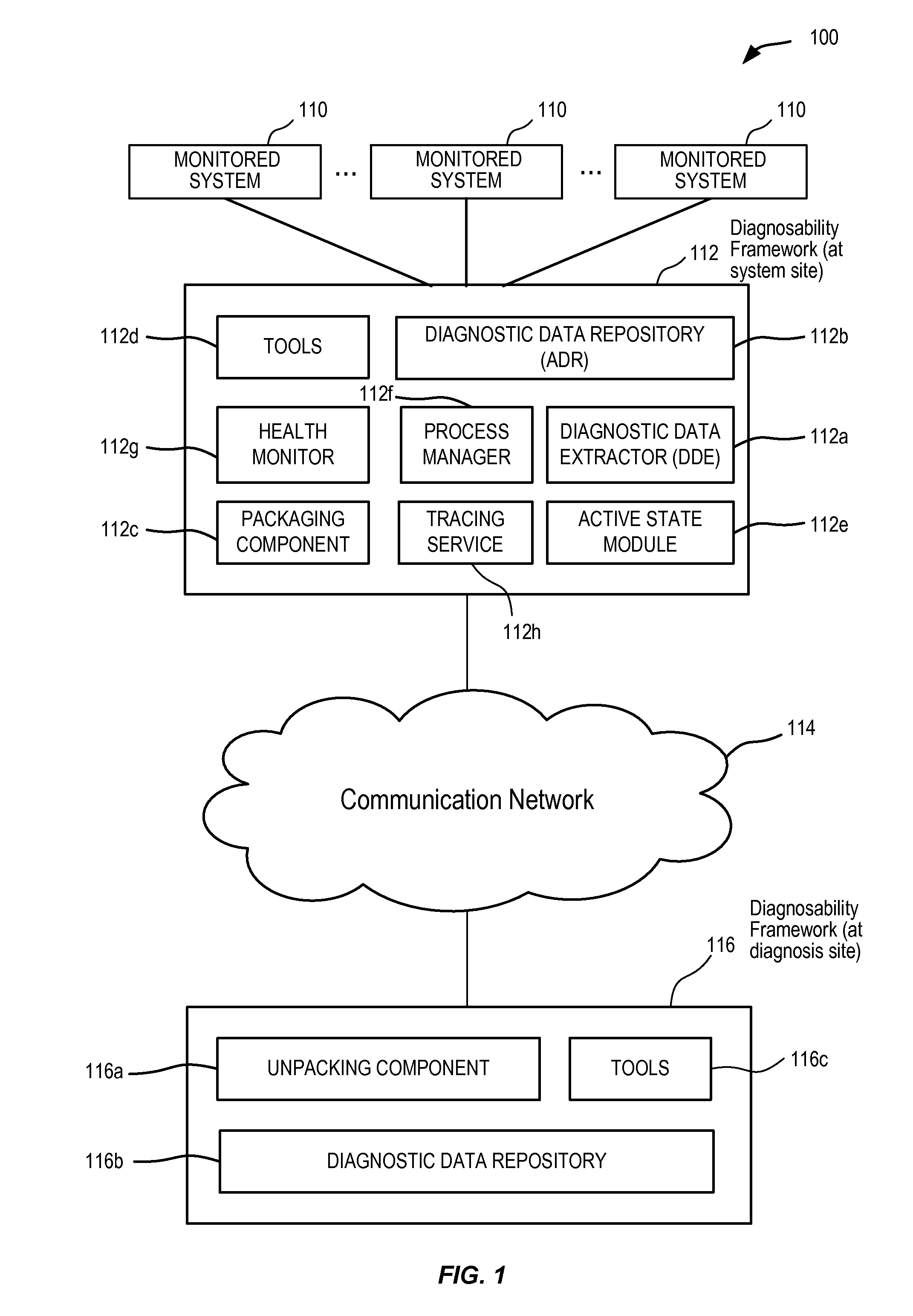
[0018]Embodiments of the present invention provide a diagnosability system for automatically collecting, storing, communicating, and analyzing diagnostic data for one or more monitored systems. The diagnosability system comprises several components configured for the collection, storage, communication, and analysis of diagnostic data for a condition detected in monitored system. The diagnosability system enables targeted dumping of diagnostic data so that only diagnostic data that is relevant for diagnosing the condition detected in the monitored system is collected and stored. This in turn enables first failure analysis thereby reducing the time needed to resolve the condition detected in the monitored system.
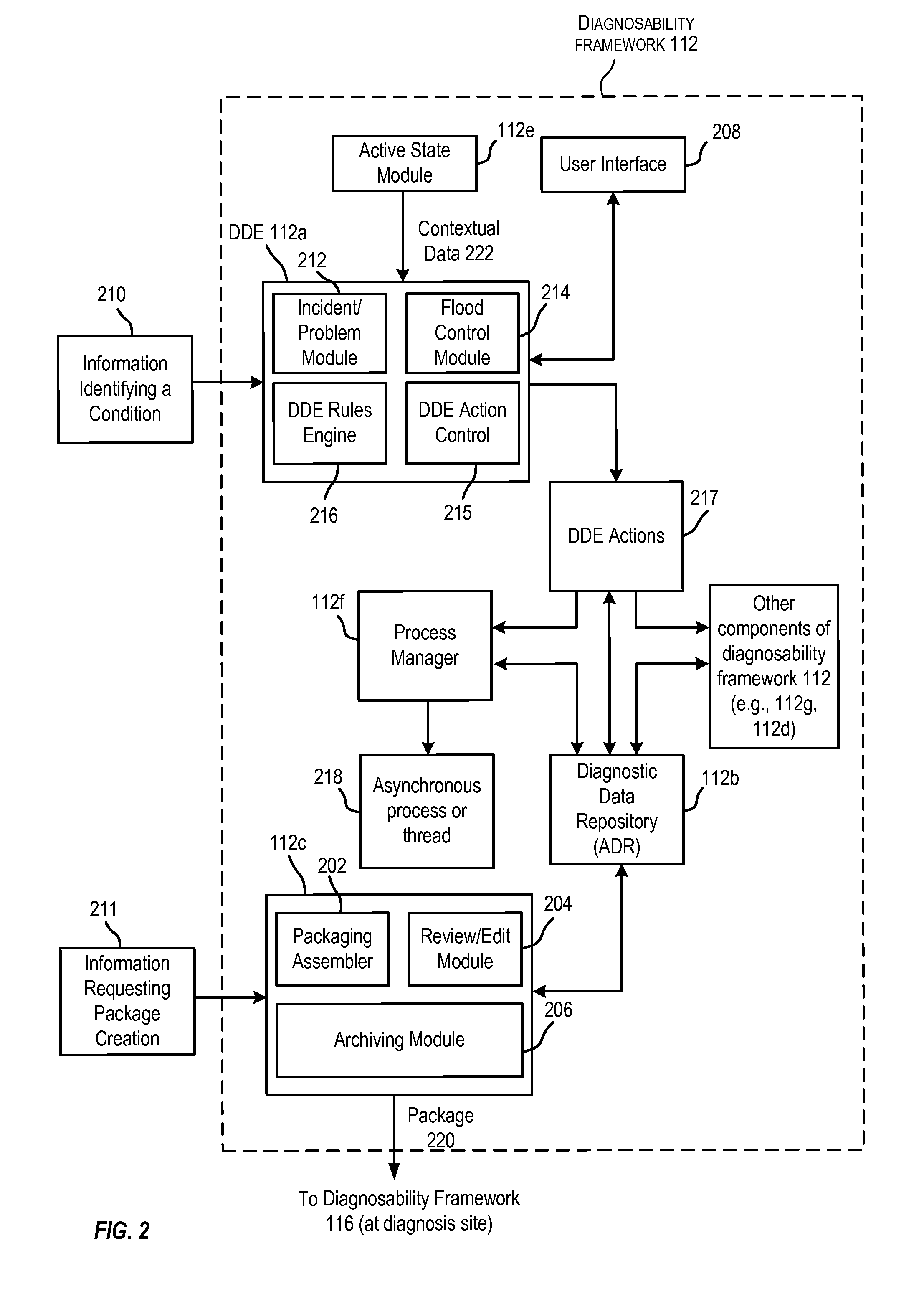
[0028]In one embodiment, an indication of the condition detected in the monitored system may be received from a first process or thread in the monitored system. A second process or thread may be initiated. The determined diagnostic action is executed in the second process or thread. The first process or thread may continue processing without being delayed or interrupted by the execution of the diagnostic action in the second process or thread.
Problems solved by technology
Such an approach of complete diagnostic data gathering however consumes a lot of time and valuable system resources.
Further, the amount of data that is collected may include thousands of files and many gigabytes of data.
Sending such a large volume of data to the diagnosis site is cumbersome, time-consuming, and expensive.
Further, if the data received at a diagnosis site is very large, it takes the vendor a long time to analyze the received diagnostic data to identify relevant pieces of data for analyzing a particular problem.
This increases the amount of time needed to diagnose the error or problem.
This process is very time-consuming and also very error-prone due to its manual component.
In addition, this process is not an efficient way to gather the required diagnostic data on the first occurrence of a failure.
As a result, the time needed to resolve the error is again increased, leading to customer dissatisfaction.
This results in a long resolution time for the failure or error.
Further, because of the manual component and because system administrators can have different skill levels, the reliability of the data gathering process is not assured and not repeatable.
Method used
Image
Click on the blue label to locate the original text in one second.
Reading with bidirectional positioning of images and text.
Examples
Embodiment Construction
[0041]In the following description, for the purposes of explanation, specific details are set forth in order to provide a thorough understanding of the invention. However, it will be apparent that the invention may be practiced without these specific details.
[0042]Embodiments of the present invention provide a diagnosability system for automatically collecting, storing, communicating, and analyzing diagnostic data for one or more monitored systems. The diagnosability system comprises several components configured for the collection, storage, communication, and analysis of diagnostic data for a condition detected in monitored system. The diagnosability system enables targeted dumping of diagnostic data so that only diagnostic data that is relevant for diagnosing the condition detected in the monitored system is collected and stored. This in turn enables first failure analysis thereby reducing the time needed to resolve the condition detected in the monitored system.
[0043]In one embod...
PUM
Abstract
A diagnosability system for automatically collecting, storing, communicating, and analyzing diagnostic data for one or more monitored systems. The diagnosability system comprises several components configured for the collection, storage, communication, and analysis of diagnostic data for a condition detected in monitored system. The diagnosability system enables targeted dumping of diagnostic data so that only diagnostic data that is relevant for diagnosing the condition detected in the monitored system is collected and stored. This in turn enables first failure analysis thereby reducing the time needed to resolve the condition detected in the monitored system.
Description
CROSS-REFERENCES TO RELATED APPLICATIONS[0001]This application claims the benefit and priority under 35 U.S.C. 119 (e) of U.S. Provisional Application Ser. No. 60 / 981,456, filed 19 Oct. 2007, entitled DIAGNOSABILITY FRAMEWORK, the contents of which are herein incorporated by reference in their entirety for all purposes.[0002]This application also incorporates by reference for all purposes the entire contents of the following related and commonly-assigned non-provisional applications, all filed concurrently with the present application:[0003](1) U.S. application Ser. No. ______ (Atty. Docket No. 021756-043710US) entitled RULE-BASED ENGINE FOR GATHERING DIAGNOSTIC DATA;[0004](2) U.S. application Ser. No. ______ (Atty. Docket No. 021756-043720US) entitled NON-INTRUSIVE GATHERING OF DIAGNOSTIC DATA USING ASYNCHRONOUS MECHANISMS.[0005](3) U.S. application Ser. No. ______ (Atty. Docket No. 021756-043711US) entitled GATHERING CONTEXT INFORMATION USED FOR ACTIVATION OF CONTEXTUAL DUMPING;[0...
Claims
Application Information
Patent Timeline
Application Date:The date an application was filed.
Publication Date:The date a patent or application was officially published.
First Publication Date:The earliest publication date of a patent with the same application number.
Issue Date:Publication date of the patent grant document.
PCT Entry Date:The Entry date of PCT National Phase.
Estimated Expiry Date:The statutory expiry date of a patent right according to the Patent Law, and it is the longest term of protection that the patent right can achieve without the termination of the patent right due to other reasons(Term extension factor has been taken into account ).
Invalid Date:Actual expiry date is based on effective date or publication date of legal transaction data of invalid patent.
Patent Type & AuthorityApplications(United States)

