Light Microscope

a light microscope and microscope technology, applied in the field of light microscopes, can solve the problems of complex mechanics, inability to sharply image the object field as a whole, and inability to achieve the effect of improving imaging quality

Inactive Publication Date: 2009-04-30
LEICA INSTR SINGAPORE PTE +1
View PDF6 Cites 4 Cited by
  • Summary
  • Abstract
  • Description
  • Claims
  • Application Information

AI Technical Summary

Benefits of technology

[0007]Thus the object of the invention is to provide a light microscope which

Problems solved by technology

In the case of the secondary observer the problem exists that due to reasons of space the objective assigned to him has to be arranged laterally from the primary observer's objective.
For one thing, this means that the object field cannot be sharply imaged as a whole and for the other that it is perspectively distorted due to the angular viewing angle.
Anot

Method used


Image

  • Light Microscope
  • Light Microscope
  • Light Microscope

Examples


Embodiment Construction

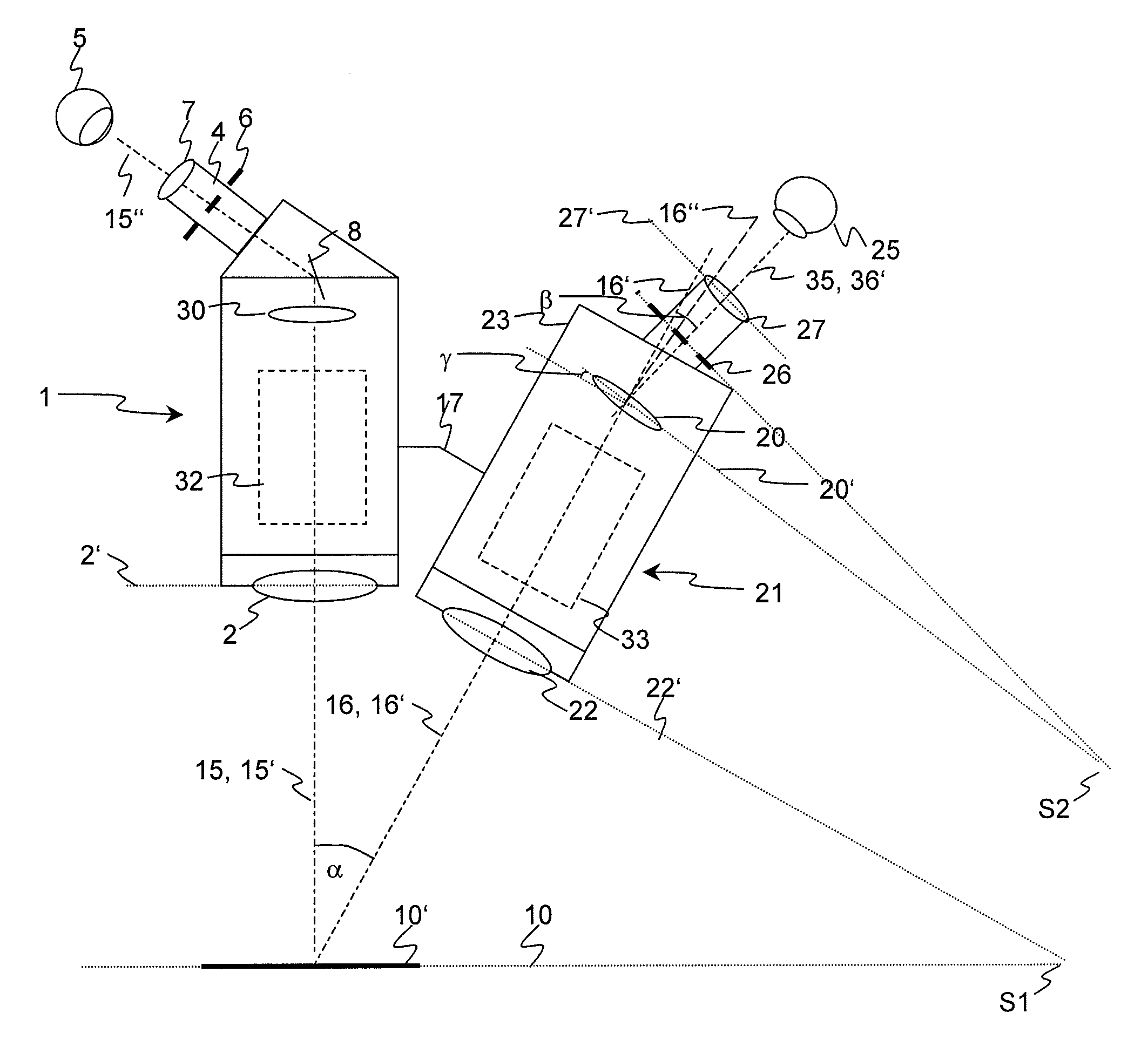
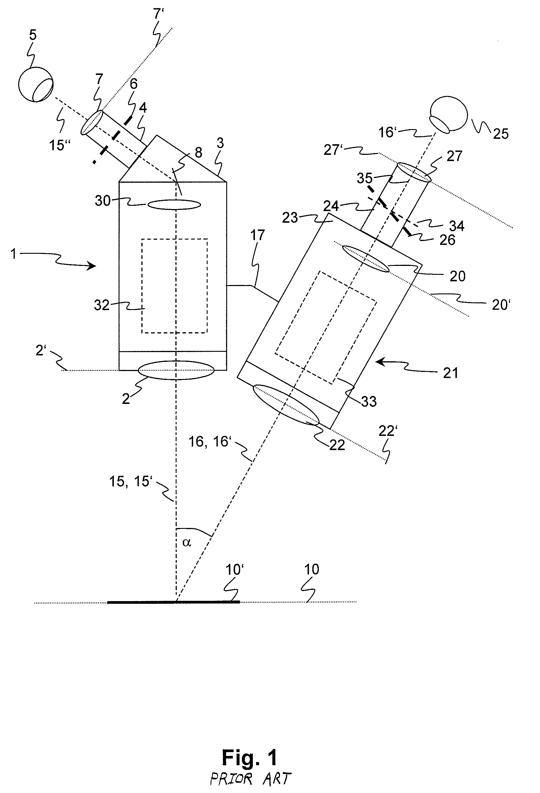
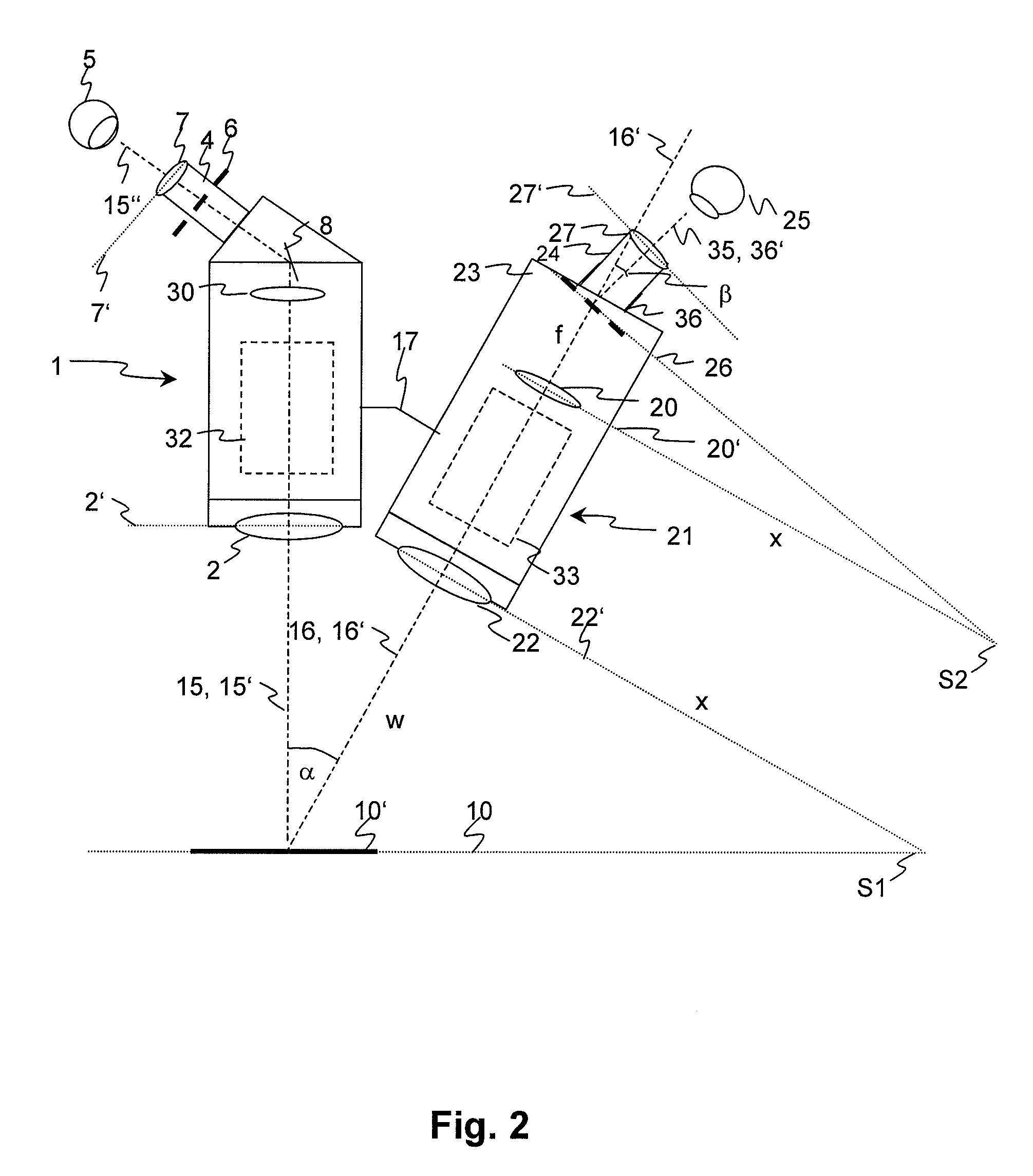
[0025]FIGS. 1 to 3 show the schematic structure of a main microscope 1 having an assistant microscope 21. The assistant microscope 21 is attached to the outside of the main microscope 1 at a fixed angle by means of a mounting fixture 17; preferably pivotable around the viewing axis 15, 15′ of the main microscope 1. The main and assistant microscope 1, 21 are in particular concerned with stereo microscopes that are used as surgical microscopes, wherein in each case only one of the two stereoscopic beam paths is shown here.

[0026]In the object plane 10 a normally circular object field 10′ is illuminated with incident light illumination by a lighting device that is not shown here. The light of the object from the object field 10′ is imaged via the objective 2 of the main microscope 1 inside the binocular tube 3 via a tube lens 30 in the eyepiece intermediate image plane 6. From there the intermediate image in the intermediate image plane 6 is projected via the eyepiece 4 with eyepiece l...


PUM


Abstract

An assistant microscope as an add-on device for a surgical microscope (1) comprises at least one objective (22) that is inclined relative to an object plane (10) with an object field (10′), in which the objective defines an objective plane (22′) and an objective axis (16′) perpendicular thereto forming an angle α of larger than 0° to the surface normal of the object plane (10). The light microscope further comprises a tube (23) and at least one eyepiece (24) having at least one eyepiece lens (27) which defines an eyepiece plane (27′) and an eyepiece axis (35) arranged perpendicular thereto. Due to the oblique viewing angle onto the object plane (10), an intermediate image plane (26) to be imaged by the eyepiece (24) is inclined relative to the objective plane (22′), on a conventional microscope it no longer corresponds to the nominal intermediate image plane. According to the invention the aberration caused by this is eliminated by the eyepiece axis (35) and the objective axis (16′) forming an angle β of larger than 0°, wherein the angle β is so chosen that the eyepiece axis (35) is substantially perpendicular to the intermediate image plane (26). In this way, the object field (10′) is imaged free of distortion and sharply across the entire image area.

Description

CROSS REFERENCE TO RELATED APPLICATIONS[0001]This application claims priority of the German patent application 10 2007 051 405.2 filed Oct. 25, 2007 which is incorporated by reference herein.FIELD OF THE INVENTION[0002]The invention relates to a light microscope of a type including an objective that is inclined relative to an object plane having an object field. The invention relates in particular to a stereo microscope as a secondary observer unit, which is used as an add-on to a primary observer microscope, such as, for example, a so-called assistant microscope used as an add-on to a surgical microscope.BACKGROUND OF THE INVENTION[0003]Surgical microscopes used in medicine, and here in particular in ophthalmology and neurosurgery should provide the means for an assistant (secondary observer) to view the same field of operation as the surgeon (primary observer). In this connection it is known to fit an independent assistant microscope on the outside of a main microscope housing. Us...

Claims


Application Information

Patent Timeline
IPC IPC(8): G02B21/22G02B21/02G02B21/18
CPCA61B3/13G02B21/18G02B21/0012
Inventor SANDER, ULRICH
Owner LEICA INSTR SINGAPORE PTE
Why Eureka
Try Eureka