Apparatus, medium and method to encode and decode high frequency signal

a high-frequency signal and high-frequency technology, applied in the field of high-frequency signal encoding or decoding, can solve the problem of greatly reducing the sound quality

Active Publication Date: 2009-04-30
SAMSUNG ELECTRONICS CO LTD
View PDF15 Cites 57 Cited by
  • Summary
  • Abstract
  • Description
  • Claims
  • Application Information

AI Technical Summary

Benefits of technology

[0007]One or more embodiment of the present general inventive concept provides an apparatus and method of encoding or

Problems solved by technology

However, when a high frequency signal is produced by simply replicating a low frequency signal and then decoded as in the conventional art, a high f

Method used


Image

  • Apparatus, medium and method to encode and decode high frequency signal
  • Apparatus, medium and method to encode and decode high frequency signal
  • Apparatus, medium and method to encode and decode high frequency signal

Examples


Embodiment Construction

[0041]An apparatus and method of encoding and decoding a high frequency signal according to the present general inventive concept will now be described more fully with reference to the accompanying drawings, wherein like reference numerals refer to like elements throughout, in which exemplary embodiments of the general inventive concept are illustrated. The embodiments are described below in order to explain the present general inventive concept by referring to the figures.

[0042]First, exemplary encoding apparatuses according to embodiments of the present general inventive concept will now be described.

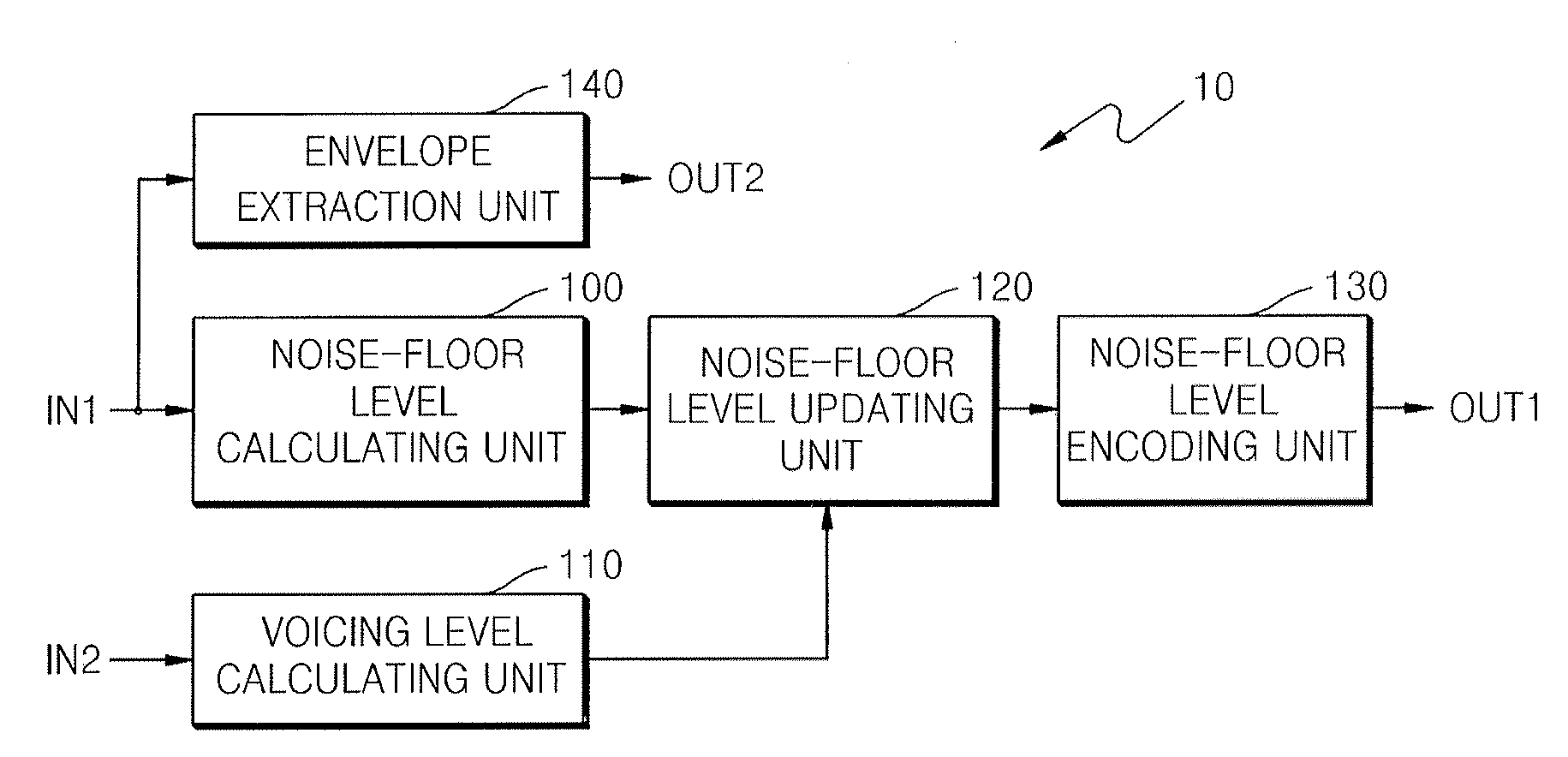
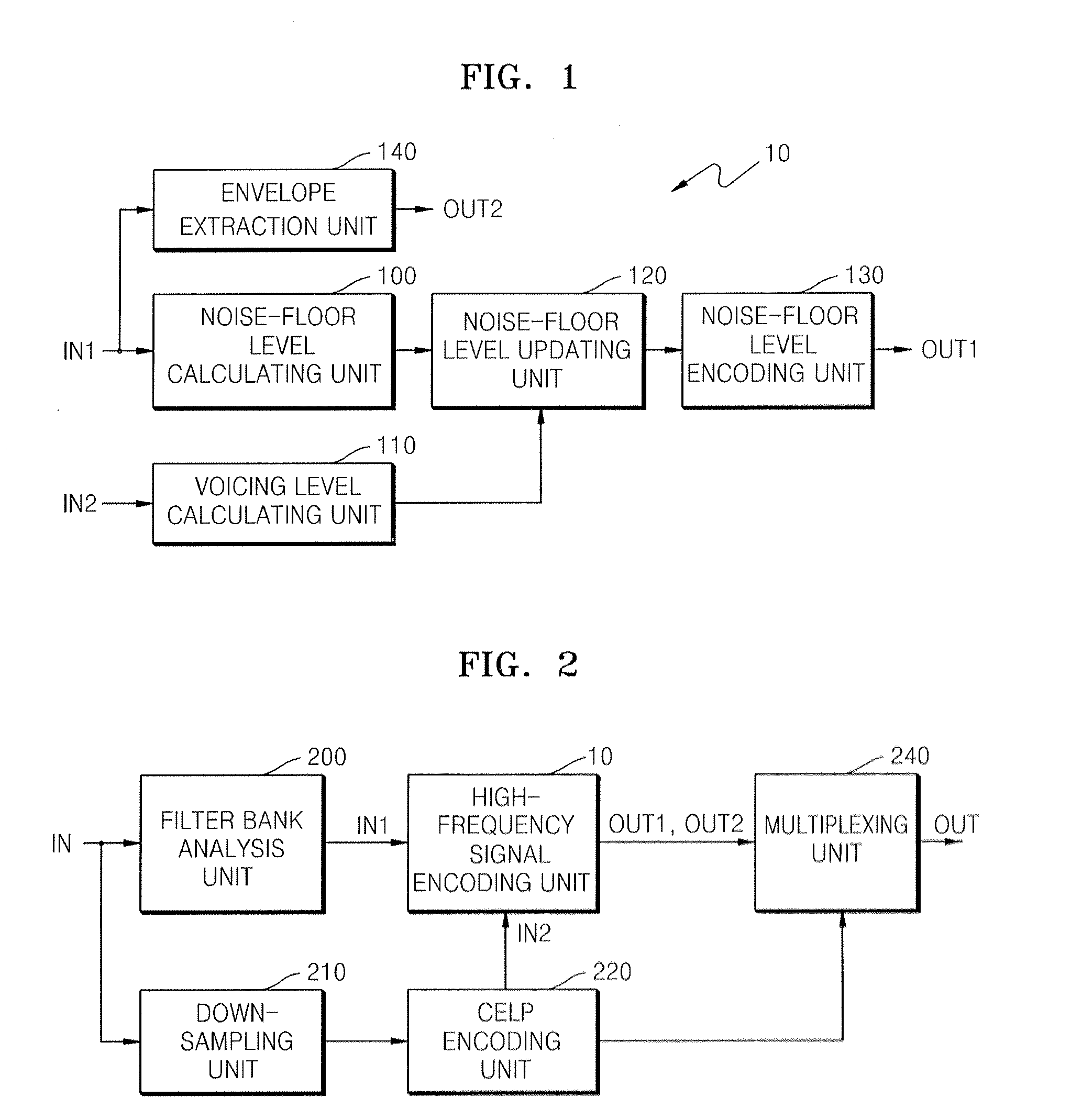
[0043]FIG. 1 is a block diagram of an exemplary high frequency signal encoding apparatus 10 according to an embodiment of the present general inventive concept. Referring to FIG. 1, the exemplary high frequency signal encoding apparatus 10 includes a noise-floor level calculating unit 100, a voicing level calculating unit 110, a noise-floor level updating unit 120, a noise-floor level...


PUM


Abstract

A method and apparatus to encoding or decoding an audio signal is provided. In the method and apparatus, a noise-floor level to use in encoding or decoding a high frequency signal is updated according to the degree of a voiced or unvoiced sound included in the signal.

Description

CROSS-REFERENCE TO RELATED APPLICATIONS[0001]This application claims the benefit of Korean Patent Application No. 10-2007-0109823, filed on Oct. 30, 2007, in the Korean Intellectual Property Office, the disclosure of which is incorporated herein in its entirety by reference.BACKGROUND OF THE INVENTION[0002]1. Field of the Invention[0003]One or more embodiment of the present general inventive concept relates to encoding or decoding an audio signal, and more particularly, to a method and apparatus to encode or decode a high frequency signal contained in a band of frequencies which is greater than a predetermined frequency.[0004]2. Description of the Related Art[0005]Audio signals, such as speech signals or music signals, can be divided into low frequency signals contained in a band of frequencies that is less than a predetermined frequency and high frequency signals contained in a band of frequencies that is greater than the predetermined frequency. Since high frequency signals are le...

Claims


Application Information

Patent Timeline
IPC IPC(8): H03B29/00G10L21/02G10L21/038G10L25/93
CPCG10L25/93G10L21/038G10L19/00G10L19/06G10L19/12
Inventor CHOO, KI-HYUNOH, EUN-MISUNG, HO-SANGKIM, JUNG-HOEKIM, MI-YOUNG
Owner SAMSUNG ELECTRONICS CO LTD
Why Eureka
Try Eureka