Ear curette

a curette and ear technology, applied in the field of ear curettes, can solve the problems of earwax accumulation between the gaps between each ring and the gap between each ring, and the ring assembly (b>20/b>) still has the sanitary problem, and achieves the effect of convenient cleaning

Inactive Publication Date: 2009-04-30
HIGHPLUS INT
View PDF3 Cites 6 Cited by
  • Summary
  • Abstract
  • Description
  • Claims
  • Application Information

AI Technical Summary

Benefits of technology

[0007]The main objective of the invention is to provide an ear curette that is easy to clean.

Problems solved by technology

Furthermore, the other rings (11) might cause sanitary problems because the gap between each two rings (11) is too narrow to be cleaned effectively, resulting in earwax accumulation between the gaps between each two rings (11).
Nevertheless, the ring assembly (20) still has the sanitary problem due to similar cleaning difficulties.

Method used


Image

  • Ear curette
  • Ear curette
  • Ear curette

Examples


Embodiment Construction

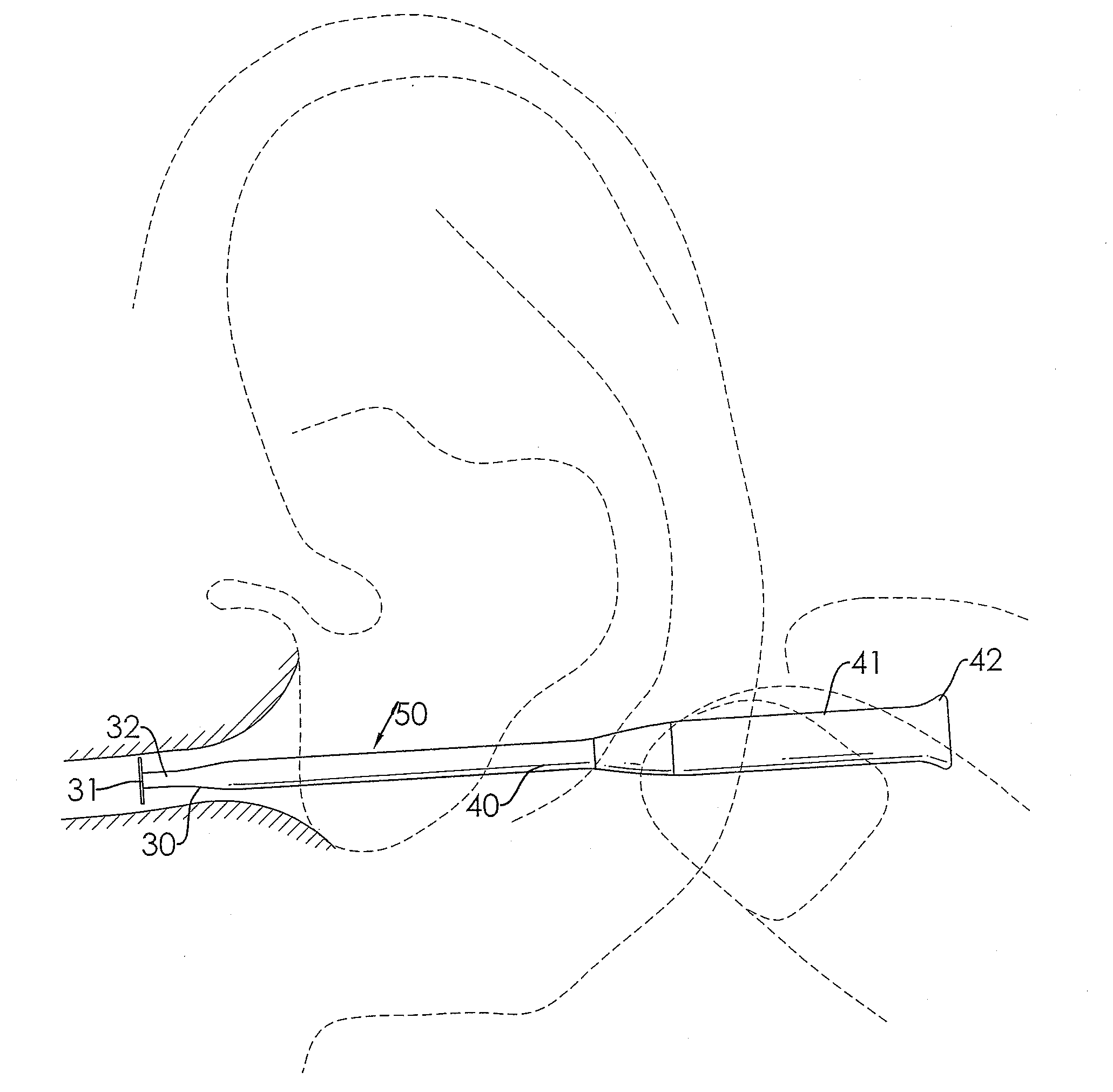
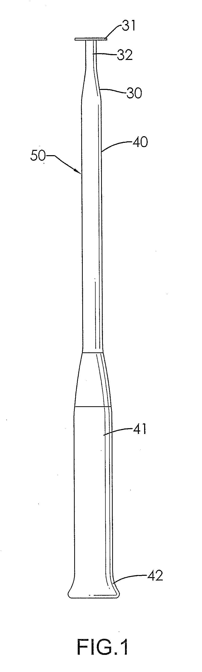
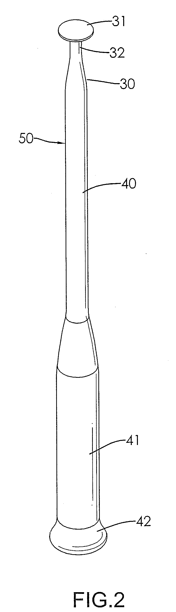
[0016]With reference to FIGS. 1, 2 and 4, an ear curette (50) in accordance with the present invention has a shaft (40) and a cleaning portion (30) and may be implemented with an optional cover (60).

[0017]The shaft (40) has a proximal end, a distal end, an optional handle (41) and an optional butt (42). The handle (41) may be cylindrical and has a distal end and a proximal end. The distal end of the handle (41) is formed on the proximal end of the shaft (40). The butt (42) is formed at the proximal end of the handle (41) and is larger than the handle (41) to aid handling.

[0018]The cleaning portion (30) has a bar (32) and a disk (31). The bar (32) is narrower than, is formed on and protrudes from the distal end of the shaft (40) and has a distal end. The disk (31) is circular and has an attaching surface and an outer surface. The attaching surface is attached to the distal end of the bar (32). The outer surface is opposite to the attaching surface and may be flat. When implemented, e...


PUM


Abstract

An ear curette has a shaft and a cleaning portion. The shaft has a distal end. The cleaning portion has a disk and a bar. The bar has a distal end and a proximal end. The proximal end of the bar is narrower than, is formed on and protrudes from distal end of the shaft. The disk is formed on the distal end of the bar. When in use, the disk of the cleaning portion can be deposited in the ear canal first and then pulled out of the ear canal to scrape out earwax and is easily cleanable.

Description

BACKGROUND OF THE INVENTION[0001]1. Field of the Invention[0002]The present invention relates to an ear curette, particularly to clean earwax from ear canals.[0003]2. Description of the Prior Arts[0004]With reference to FIG. 5, a conventional ear curette is used to clear wax build up from an ear canal and consists of a shaft (12) and a ring assembly (10). The shaft (12) has a distal end and a proximal end. The ring assembly (10) is mounted around the distal end of the shaft (12) and may be a rigid material and may be further coated with a resilient material such as rubber or the like. The ring assembly (10) consists of multiple parallel rings (11). The parallel rings (11) are mounted around the distal end of the shaft (12). Each two of the rings (11) define a gap for accommodating earwax so as to be scraped out from the ear canal by withdrawing the shaft (12). However, only one ring (11) being most proximal to the distal end, of the shaft (12) effectively scrapes earwax from the ear...

Claims


Application Information

Patent Timeline
Patent Type & Authority Applications(United States)
IPC IPC(8): A61F11/00
CPCA61F11/006
Inventor KAO, YU-YUEH
Owner HIGHPLUS INT
Why Eureka
Try Eureka