
Metal construction member

a technology of construction members and metal sheets, applied in the direction of girders, joists, trusses, etc., can solve the problems of high cost of manufacture, inability to use in place of standard-sized wall studs, and the specific material used to fabricate construction members, and the shape, thickness and yield strength of these materials have never been optimized with respect to price and performance, and achieve the effect of reducing the thickness dimension of high-yield steel sheets and high yield strength

Inactive Publication Date: 2009-05-07
SUPREME FRAMING SYST
View PDF12 Cites 21 Cited by
  • Summary
  • Abstract
  • Description
  • Claims
  • Application Information

AI Technical Summary

Benefits of technology

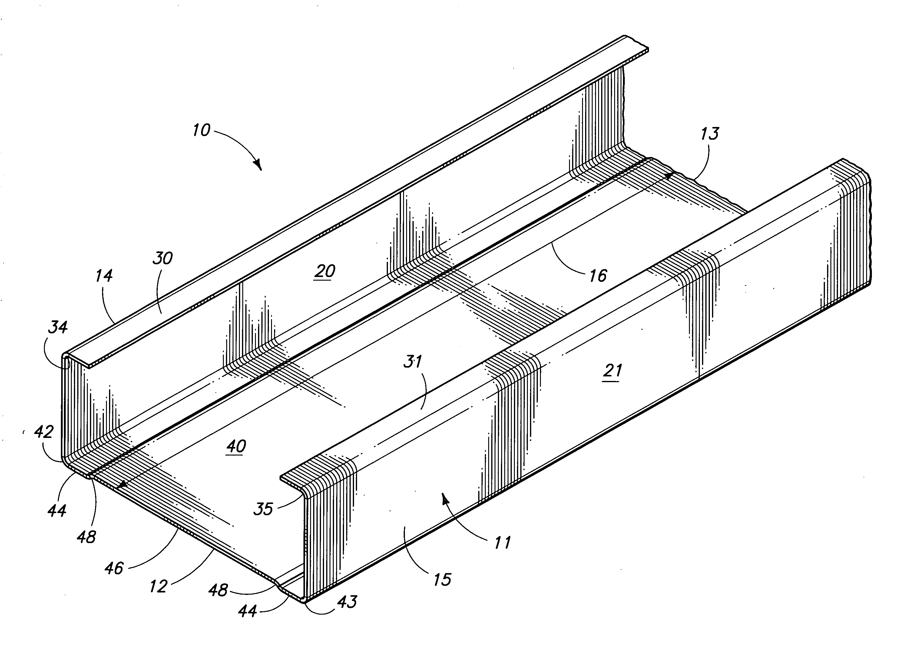
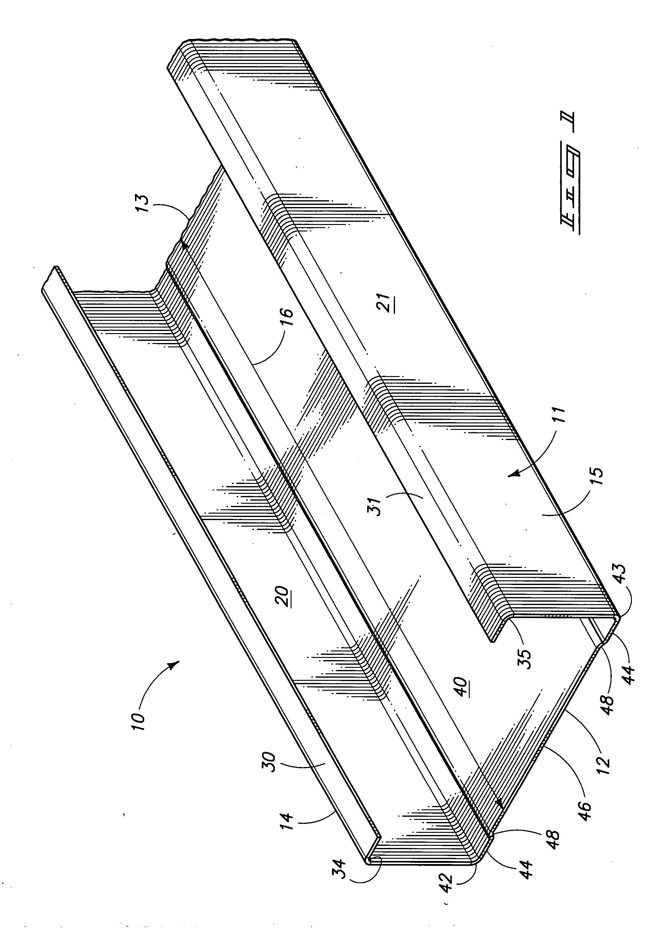
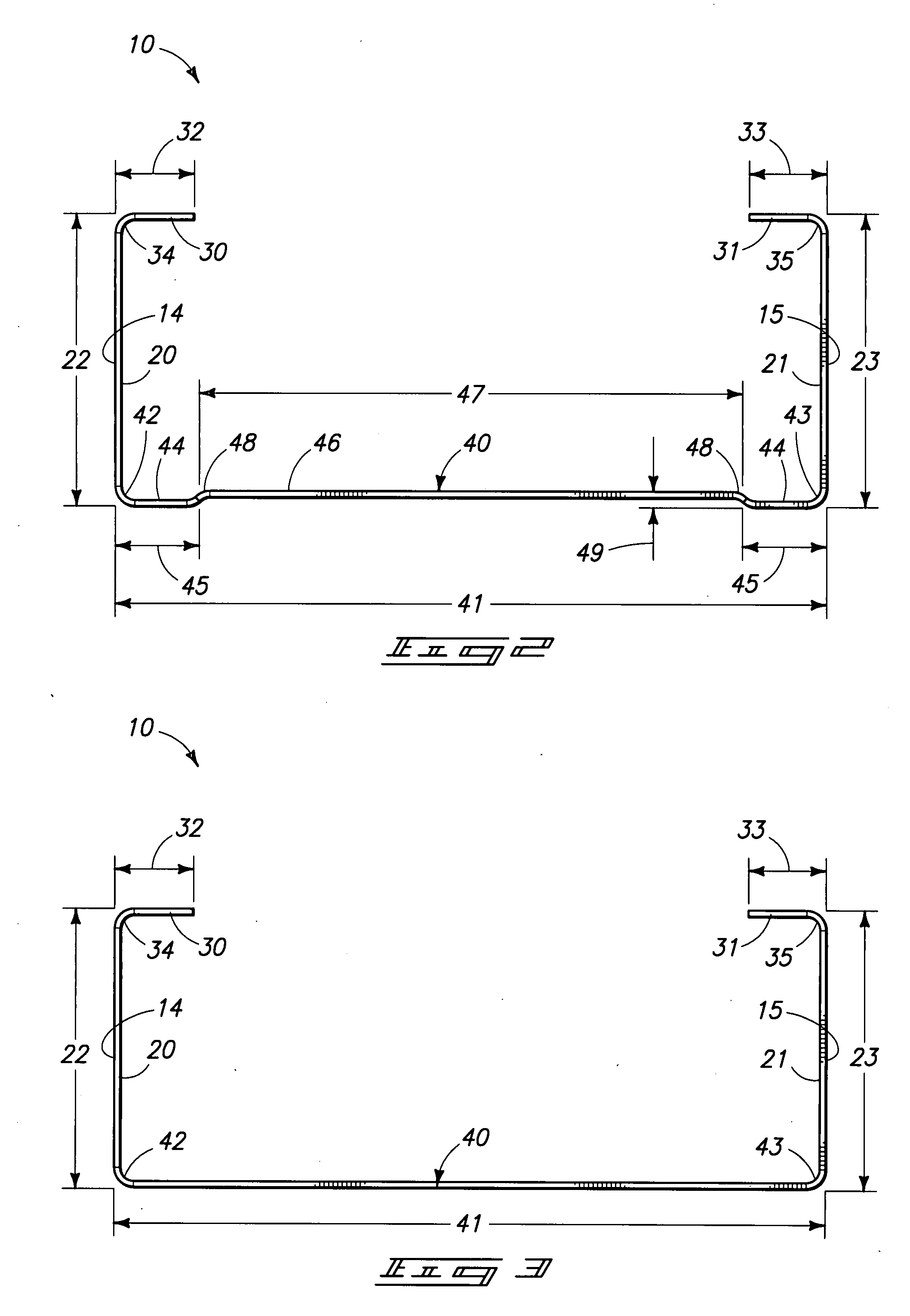
[0007]Yet another aspect of the present invention relates to a metal construction member for non load bearing construction applications which has a C-shaped main body which is defined by a web portion which has opposite, longitudinally extending peripheral edges; a pair of flange members which are made integral with the web portion and which individually extend substantially normally upwardly relative to the opposite, longitudinally extending peripheral edges of the web portion; and a pair of return members which are individually made integral with the respective flange portions and which are oriented in substantially parallel spaced relation relative to the web portion. The main body is fabricated from a high yield steel sheet which has a thickness dimension of about 0.015 inches to about 0.045 inches, and a yield strength of about 57 ksi to about 65 ksi, and wherein as the yield strength of the high yield strength steel sheet increases the thickness dimension of the high yield steel sheet decreases.

Problems solved by technology

The specific material used to fabricate construction members, and the shape, thickness and yield strengths of these materials, has never been optimized with respect to price and performance.
This prior art construction member, however, is overly complex, and expensive to manufacture, and would be difficult to utilize in place of a standard-sized wall stud.
Furthermore, the use of high strength steel for the fabricating of metal studs has not been favored by manufacturers because of the higher costs associated with the material, and the associated difficulties of fastening wall board and the like to this material by employing self tapping screws which are applied by powered screw fastening tools.

Method used


Image

  • Metal construction member
  • Metal construction member
  • Metal construction member

Examples


Embodiment Construction

[0013]This disclosure of the invention is submitted in furtherance of the constitutional purposes of the U.S. Patent Laws “to promote the progress of science and useful arts” (Article 1, Section 8).

[0014]Referring now to FIGS. 1-3, a construction member which is the subject of the present invention is generally indicated by the numeral 10. The construction member as shown depicts two possible forms of a “C-profile” or “C-shaped” wall stud, although one skilled in the art will recognize that the teachings of the present invention may also be applied to the fabrication of other metal construction members such as trusses, braces, and the like. The construction member 10 may be a wall stud, a floor or ceiling truss or brace, or any other construction member used in a commercial, industrial, or residential construction. Further, the construction member 10 may be used as either a load bearing or a non-load bearing member. In FIGS. 1-3, the construction member 10 is generally shown with a ...


PUM

PropertyMeasurementUnit
yield strengthaaaaaaaaaa
thicknessaaaaaaaaaa

Abstract

A metal construction member is disclosed in which the main body is fabricated from a high yield steel sheet which has a thickness dimension of about 0.015 inches to about 0.045 inches, and a yield strength of about 57 ksi to about 65 ksi, and has a cross sectional shape which imparts increased strength to the metal construction member.

Description

TECHNICAL FIELD[0001]The present invention relates to a metal construction member, and more specifically, to a metal construction member fabricated from a high yield strength steel with a reduced thickness dimension.BACKGROUND OF THE INVENTION[0002]The use of metal construction members, such as studs, trusses, braces, and the like, has become increasingly popular and necessary in commercial, industrial, and even residential structures. Metal studs are dimensionally stable, lightweight and quite strong, and building codes will often require the use of metal framing members for both interior and exterior walls. These metal studs are joined together by screws or other fasteners to provide walls upon which wallboard is then attached by screws. They may further have apertures formed therein and which allow electrical and plumbing conduits to pass therethrough.[0003]The specific material used to fabricate construction members, and the shape, thickness and yield strengths of these material...

Claims


Application Information

Patent Timeline
Patent Type & Authority Applications(United States)
IPC IPC(8): E04C3/09E04C3/10E04B1/24
CPCE04C2003/0473E04C3/07
Inventor STONE, LAWRENCE BPETERSON, NEAL L.
Owner SUPREME FRAMING SYST
Learn More