Drive Method for an Electrophoretic Display Device and an Electrophoretic Display Device

a technology of display device and drive method, which is applied in the direction of electric digital data processing, instruments, computing, etc., can solve the problem of time-consuming writing display and achieve the effect of sufficient reflectance and flicker suppression

Active Publication Date: 2009-05-07
E INK CORPORATION
View PDF18 Cites 14 Cited by
  • Summary
  • Abstract
  • Description
  • Claims
  • Application Information

AI Technical Summary

Benefits of technology

[0012]The drive method for an electrophoretic display device and the electrophoretic display device according to the present invention suppress flicker and achieve sufficient reflectance (contrast) with a single write operation.

Problems solved by technology

If a pulse with a relatively long pulse width is applied in the first half of the display redrawing process, flicker results because of the sudden color change at the beginning of the drive period in a variable common electrode drive method.
Flicker can be prevented by applying pulses with a short pulse width, but writing the display then becomes time consuming.

Method used


Image

  • Drive Method for an Electrophoretic Display Device and an Electrophoretic Display Device
  • Drive Method for an Electrophoretic Display Device and an Electrophoretic Display Device
  • Drive Method for an Electrophoretic Display Device and an Electrophoretic Display Device

Examples


embodiment 1

[0071]A first embodiment of the invention is described next with reference to FIG. 1 to FIG. 11.

[0072]1. General Configuration

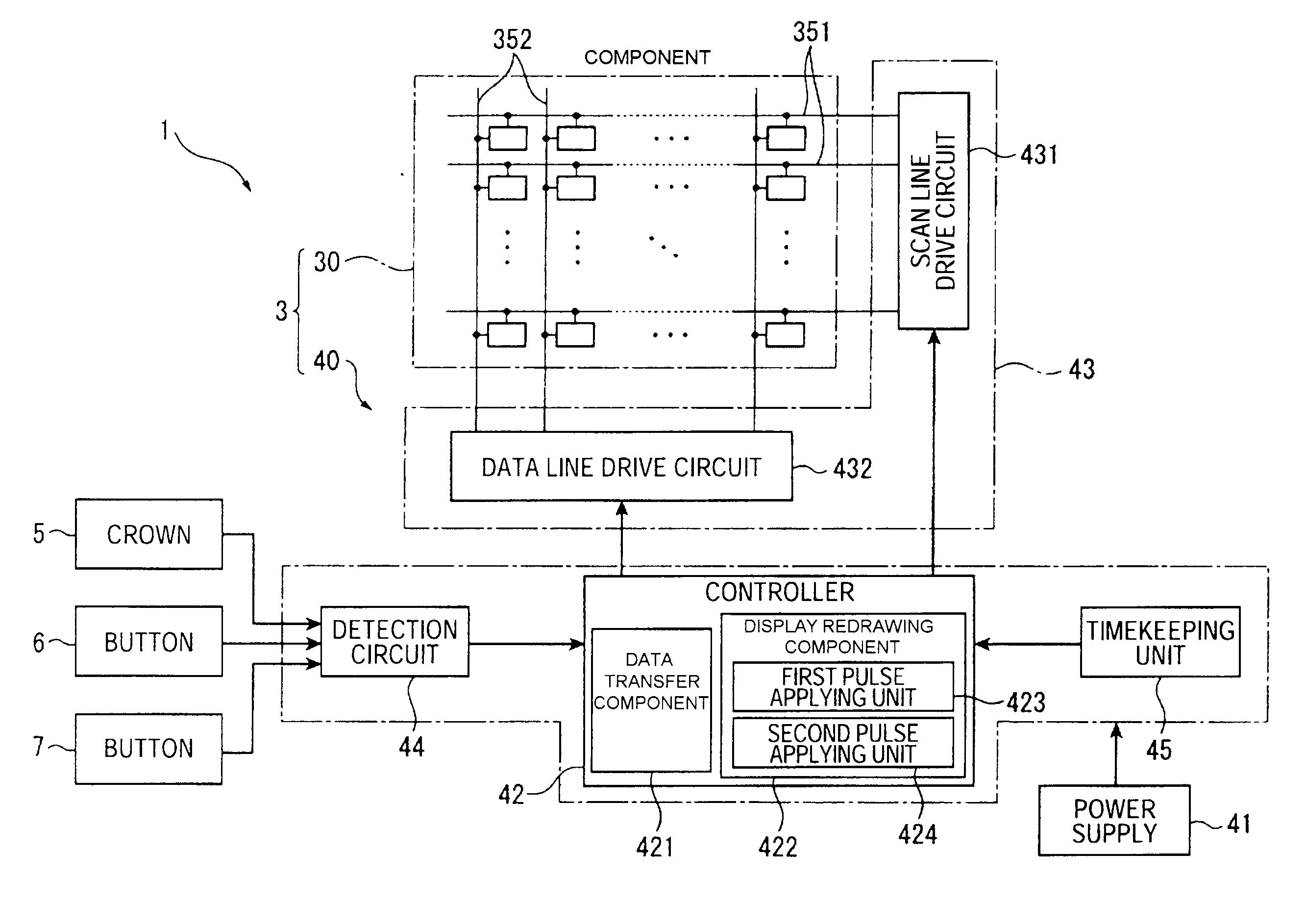
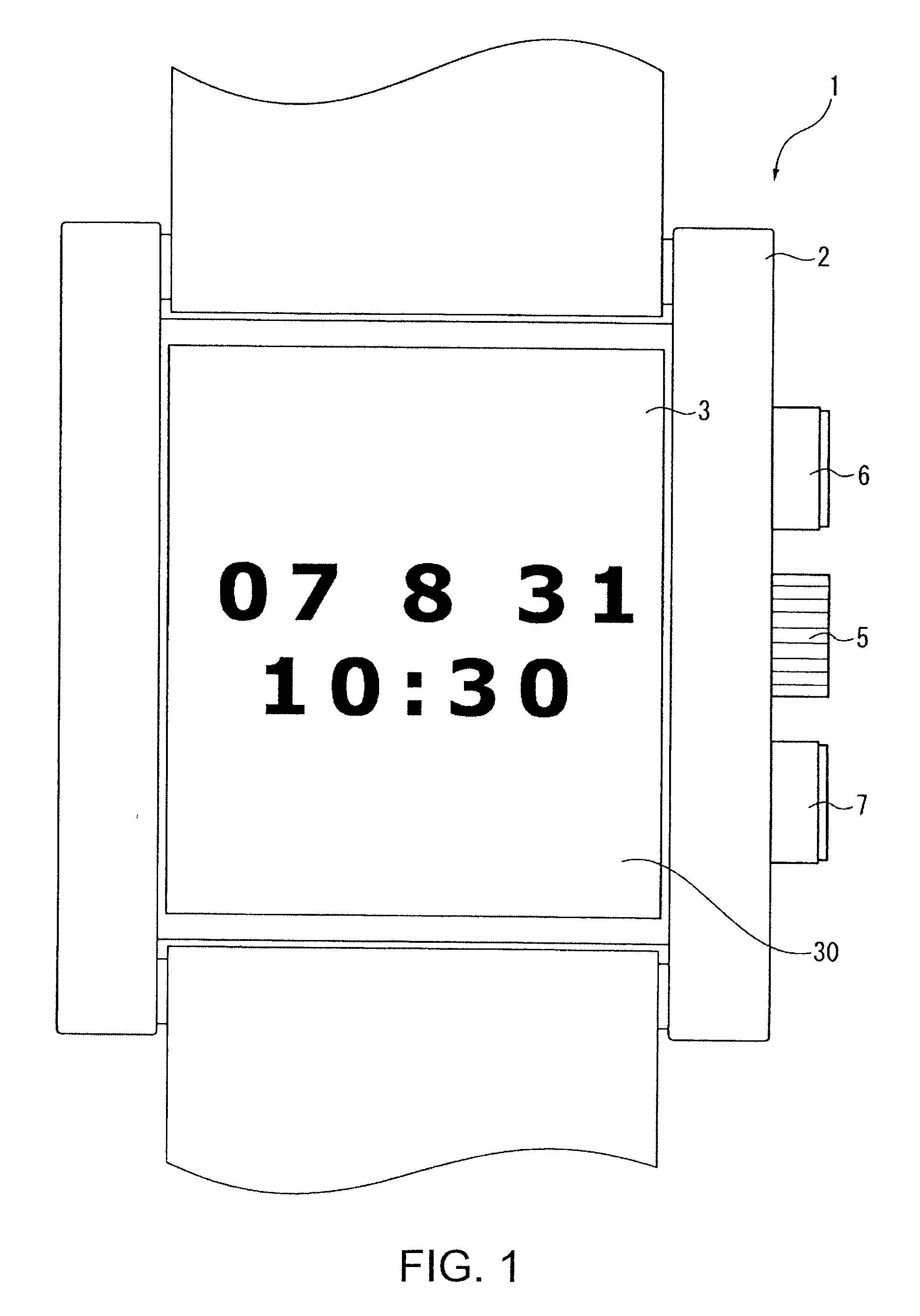
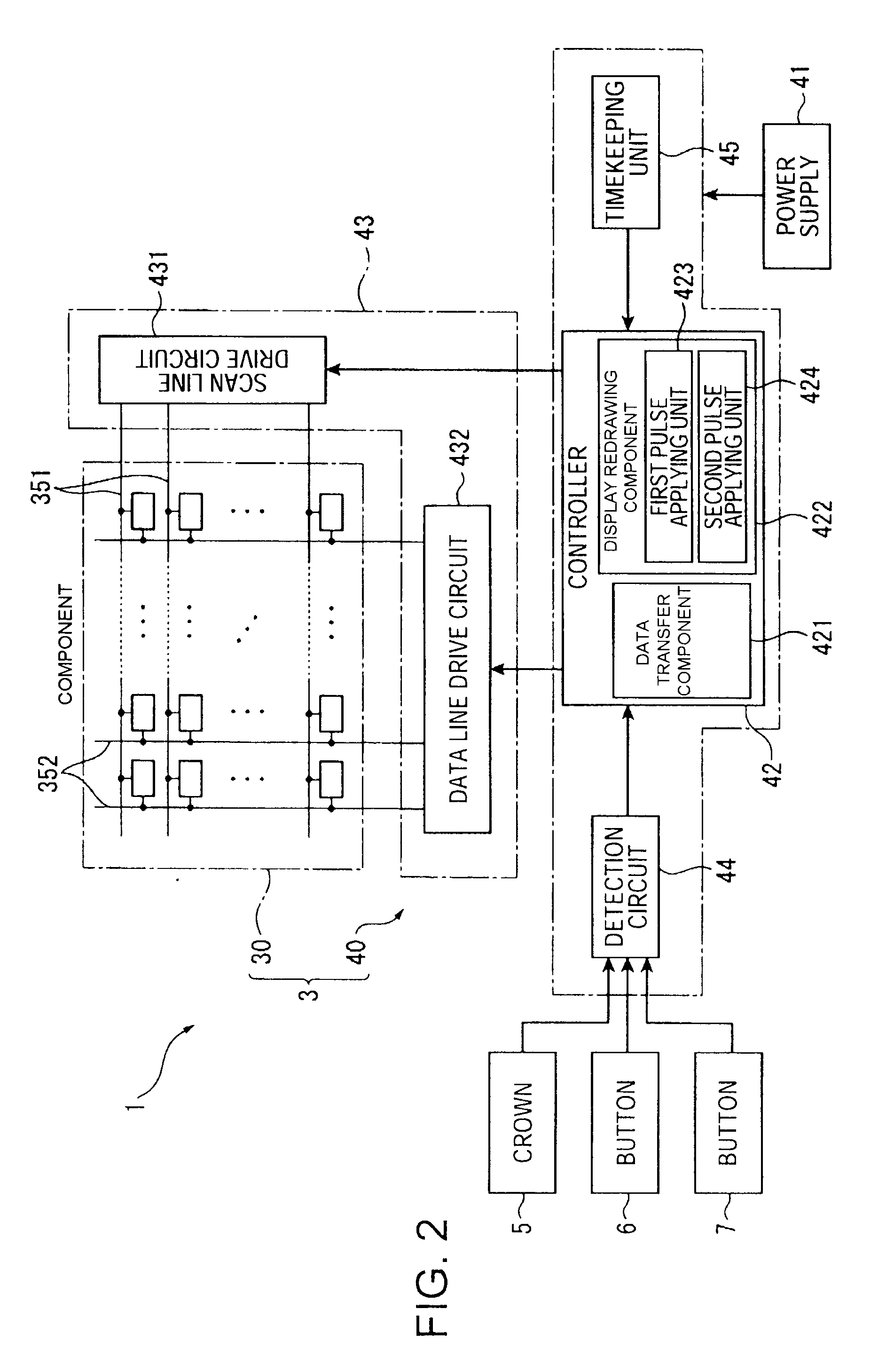
[0073]FIG. 1 is a front view of an electronic timepiece 1 that uses an electrophoretic display device according to a preferred embodiment of the invention. The electronic timepiece 1 has a rectangular case 2 and an electrophoretic display device 3. A crown 5, and buttons 6 and 7 are disposed to the case 2.

[0074]2. Electrophoretic Display Device

[0075]As shown in FIG. 2 the electrophoretic display device 3 includes a display panel 30 and a drive controller 40 that drives the display panel 30 and includes a timekeeping unit.

[0076]3. Drive Controller

[0077]The drive controller 40 includes a power supply 41, a controller 42 that controls the timepiece 1, a drive circuit 43, a detection circuit 44, and a timekeeping unit 45.

[0078]The drive circuit 43 is rendered by a driver IC and controls displaying content on the display panel 30.

[0079]The detection circuit 44 det...

embodiment 2

[0159]A timepiece according to a second embodiment of the invention is described next.

[0160]The timepiece according to this second embodiment of the invention differs from the timepiece of the first embodiment in that the number of drive pulses applied by the controller42, and specifically the number of second pulses input in the second pulse application step S22, differs from the number of pulses applied in the first embodiment as shown in FIG. 12. Other aspects of this embodiment are the same as in the first embodiment, and further description thereof is omitted or simplified.

[0161]The controller 42 controls updating the display according to the flow charts shown in FIG. 7 and FIG. 8 and described in the first embodiment above.

[0162]As shown in FIG. 12, the controller 42 (first pulse applying unit 423) controls the first pulse application step S21 as described in the first embodiment. A first pulse is therefore applied to the common electrode 32, a high signal is applied to the pi...

embodiment 3

[0172]A timepiece according to a second embodiment of the invention is described next.

[0173]The timepiece according to this third embodiment of the invention differs from the timepiece of the first and second embodiments in that the number of drive pulses applied by the controller 42, and specifically the number of second pulses input in the second pulse application step S22, differs from the number of pulses applied in the first and second embodiments as shown in FIG. 14. Other aspects of this embodiment are the same as in the first and second embodiments, and further description thereof is omitted or simplified.

[0174]The controller 42 controls updating the display according to the flow charts shown in FIG. 7 and FIG. 8 and described in the first embodiment above.

[0175]As shown in FIG. 14, the controller 42 controls the first pulse application step S21 as described in the first embodiment. A first pulse is therefore applied to the common electrode 32, a high signal is applied to th...


PUM


Abstract

A drive method for an electrophoretic display device that has an electrophoretic device composed of a suspension fluid containing electrophoretic particles disposed between a common electrode and a plurality of pixel electrodes, a driver that drives the electrophoretic device by applying voltage between the common electrode and the plural pixel electrodes, and a controller that controls the driver. The control method has a display redrawing process that changes the displayed image by applying a common electrode drive pulse that repeats two different potentials to the common electrode, and applying either of the two different potentials to the pixel electrodes according to the updated display content. The display redrawing process includes a first pulse application step that applies a first pulse train to the common electrode as the common electrode drive pulse train, and a second pulse application step that executes after the first pulse application step to apply a second pulse train to the common electrode as the common electrode drive pulse train, the pulses of the second pulse train being wider than the pulses of the first pulse train.

Description

CROSS-REFERENCE TO RELATED APPLICATIONS[0001]Japanese Patent application No.(s) 2007-286313, and 2008-160463, are hereby incorporated by reference in their entirety.BACKGROUND[0002]1. Field of Invention[0003]The present invention relates to a drive method for an electrophoretic display device and to an electrophoretic display device.[0004]2. Description of Related Art[0005]Electrophoresis, a technique in which Coulomb's force is used to cause electrophoretic particles to migrate by applying an electric field to a suspension fluid having electrophoretic particles dispersed in a fluid, and electrophoretic display devices that operate by means of electrophoresis, are known from the literature. There is, however, still room for improvement with respect to electrophoretic display devices.[0006]A common drive method used in liquid crystal displays and other types of display devices is to vary the potential of the pixel electrode while also changing the potential of the common electrode (a...

Claims


Application Information

Patent Timeline
Patent Type & Authority Applications(United States)
IPC IPC(8): G06F3/038
CPCG09G3/344G09G2300/08G09G2320/0252G09G2320/0247G09G3/2018G09G2310/068
Inventor INOUE, KATSUTOYO
Owner E INK CORPORATION
Why Eureka
Try Eureka