Method and apparatus for minimizing interference between seismic systems

Active Publication Date: 2009-05-07
CONOCOPHILLIPS CO
View PDF14 Cites 22 Cited by
  • Summary
  • Abstract
  • Description
  • Claims
  • Application Information

AI Technical Summary

Problems solved by technology
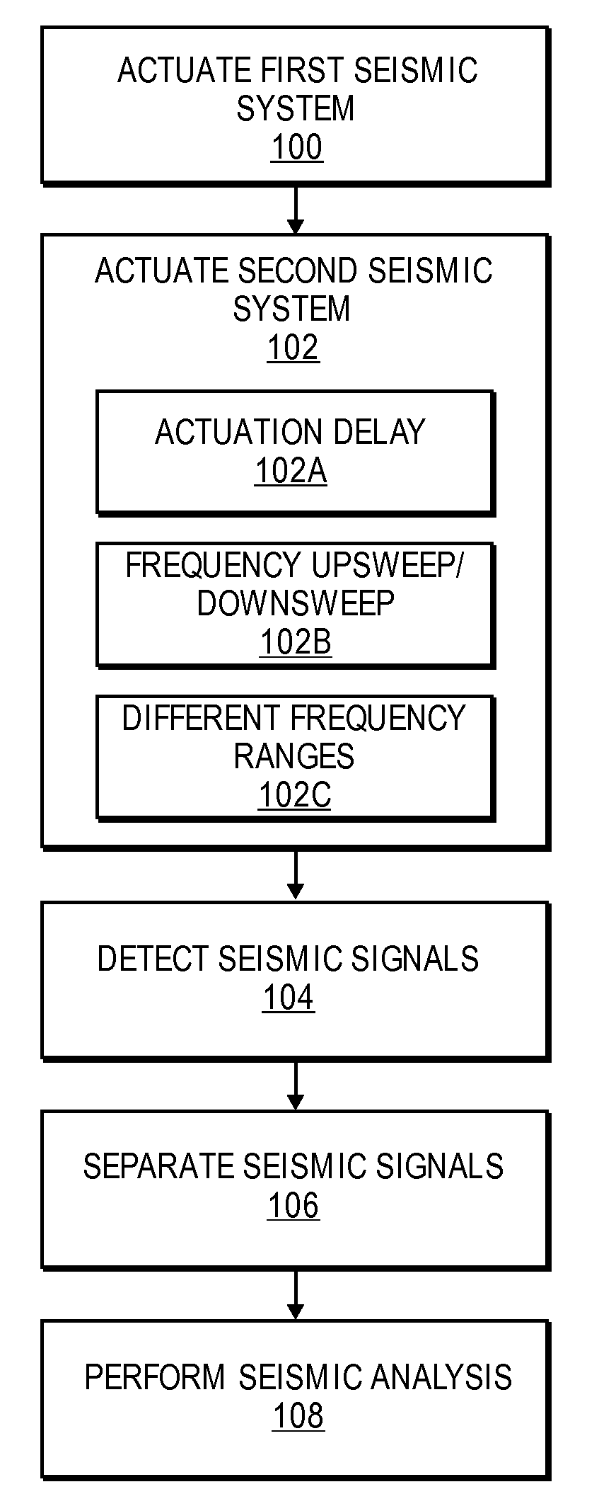
Often, it is difficult or impossible to utilize more than one multiple source and receiver

Method used


Image

  • Method and apparatus for minimizing interference between seismic systems
  • Method and apparatus for minimizing interference between seismic systems
  • Method and apparatus for minimizing interference between seismic systems

Examples


Embodiment Construction

[0028]The following detailed description of various embodiments of the invention references the accompanying drawings which illustrate specific embodiments in which the invention can be practiced. The embodiments are intended to describe aspects of the invention in sufficient detail to enable those skilled in the art to practice the invention. Other embodiments can be utilized and changes can be made without departing from the scope of the present invention. The following detailed description is, therefore, not to be taken in a limiting sense. The scope of the present invention is defined only by the appended claims, along with the full scope of equivalents to which such claims are entitled.

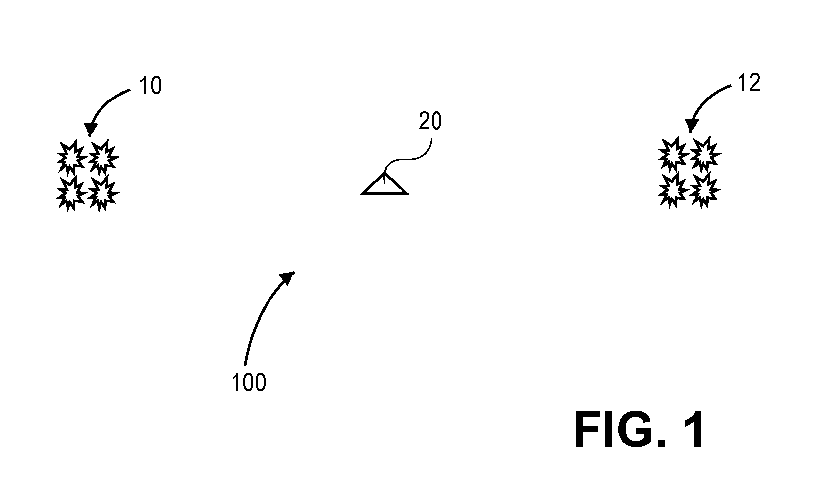
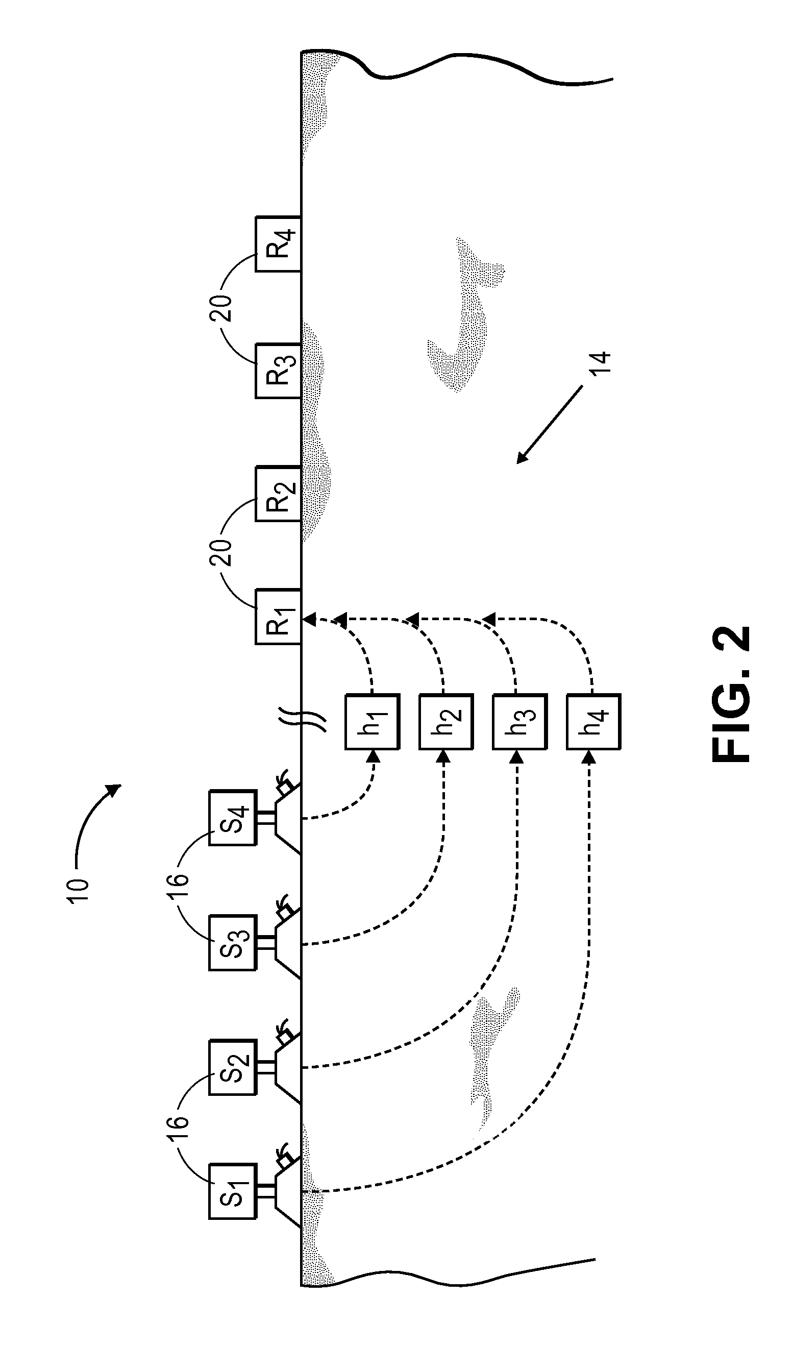
[0029]Referring initially to FIGS. 1-3, a first exemplary seismic system 10 and a second exemplary seismic system 12 are illustrated that may generate data for use by various embodiments of the present invention. In some embodiments, the seismic systems 10, 12 may cooperate to form an apparatus 1...


PUM


Abstract

A method and apparatus for minimizing interference between seismic systems. The method may generally include: (a) actuating a plurality of first sources associated with a first seismic system to generate a first plurality of phase-encoded vibratory signals; (b) actuating a plurality of second sources associated with a second seismic system to generate a second plurality of phase-encoded vibratory signals that are at least partially frequency separated from the first plurality of phase-encoded vibratory signals generated in (a); and (c) detecting the first and second plurality of phase-encoded vibratory signals utilizing a first receiver positioned at a location remote from the first and second sources.

Description

BACKGROUND OF THE INVENTION[0001]1. Field of the Invention[0002]Embodiments of the present invention relate generally to methods and apparatuses for minimizing interference between seismic systems. Particularly, various embodiments of the present invention minimize interference between seismic systems by frequency separating vibratory signals generated by the seismic systems.[0003]2. Description of the Related Art[0004]Multiple source and receiver seismic systems, often referred to in the art as high fidelity vibratory source (HFVS) or ZenSeis™ systems, can be utilized to generate seismic surveys of subterranean regions of the earth to facilitate in the recovery of various hydrocarbon resources. Multiple source and receiver seismic systems simultaneously generate a plurality of vibrations which, after reflecting or refracting from subterranean features, are measured by a plurality of receivers. Utilizing the receiver measurements and measurements made at the vibrating sources, a mat...

Claims


Application Information

Patent Timeline
IPC IPC(8): G01V1/00
CPCG01V1/005
Inventor CHIU, STEPHEN K.BREWER, JOEL D.EICK, PETER M.
Owner CONOCOPHILLIPS CO
Why Eureka
Try Eureka