Abnormality detection method for gas laser oscillator and gas laser oscillator for implementing the method

a technology of laser oscillator and gas laser, which is applied in the direction of laser details, electrical equipment, active medium materials, etc., can solve the problems of difficult to detect the abnormal discharge load

Inactive Publication Date: 2009-05-07
FANUC LTD
View PDF2 Cites 12 Cited by
  • Summary
  • Abstract
  • Description
  • Claims
  • Application Information

AI Technical Summary

Problems solved by technology

However, it is difficult, to detect the abnormality of the discharge load at the time of discharge in case of Japanese Unexamined Patent Publication No. 7-221378.
Further, according to the method disclosed by Japanese Unexamined Patent Publication No. 7-221378 in which the matching is adjusted, it is difficult to detect the abnormality of the discharge in the case where the change that has occurred is not adequate to extinguish the discharge.

Method used


Image

  • Abnormality detection method for gas laser oscillator and gas laser oscillator for implementing the method
  • Abnormality detection method for gas laser oscillator and gas laser oscillator for implementing the method
  • Abnormality detection method for gas laser oscillator and gas laser oscillator for implementing the method

Examples


first embodiment

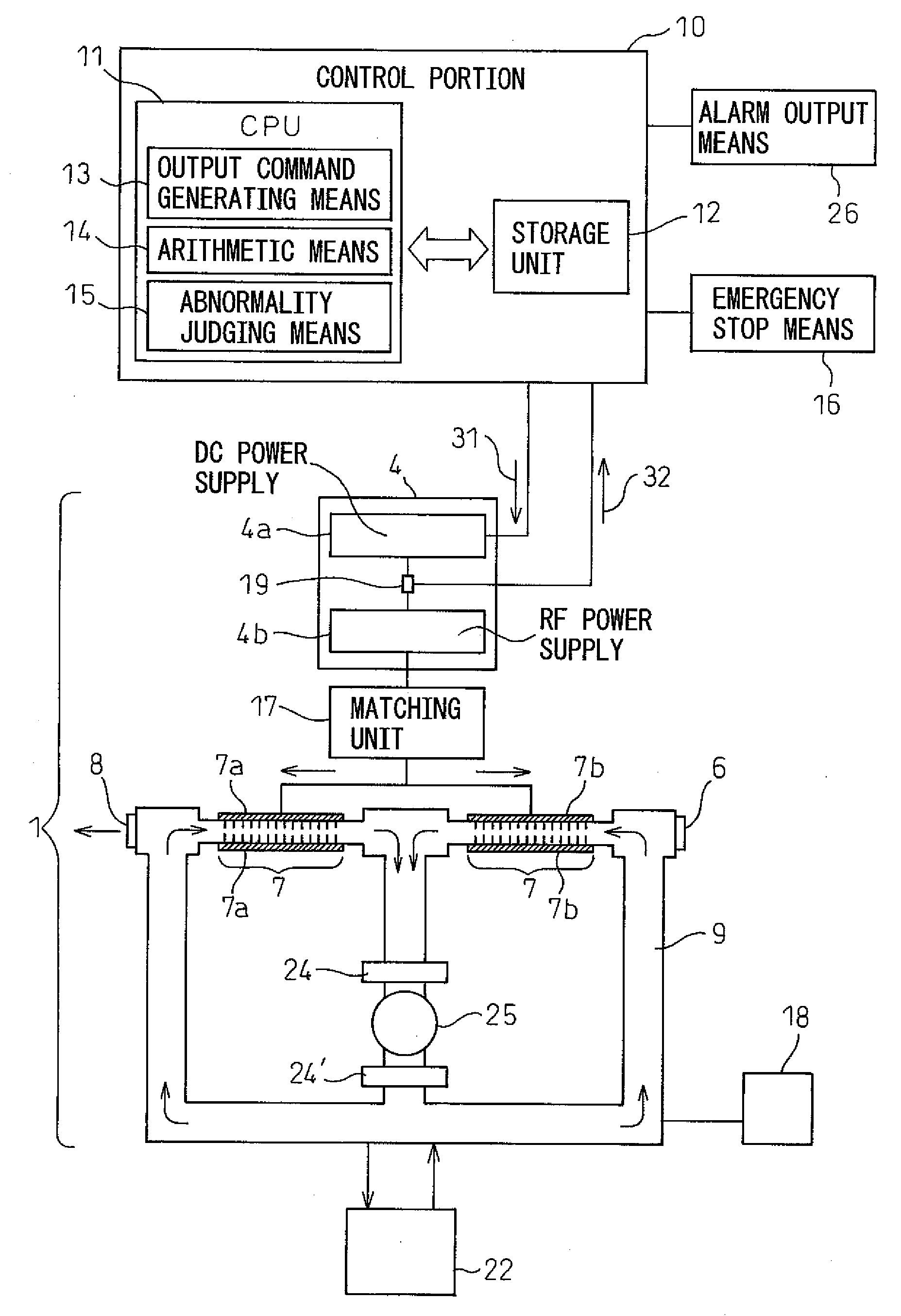
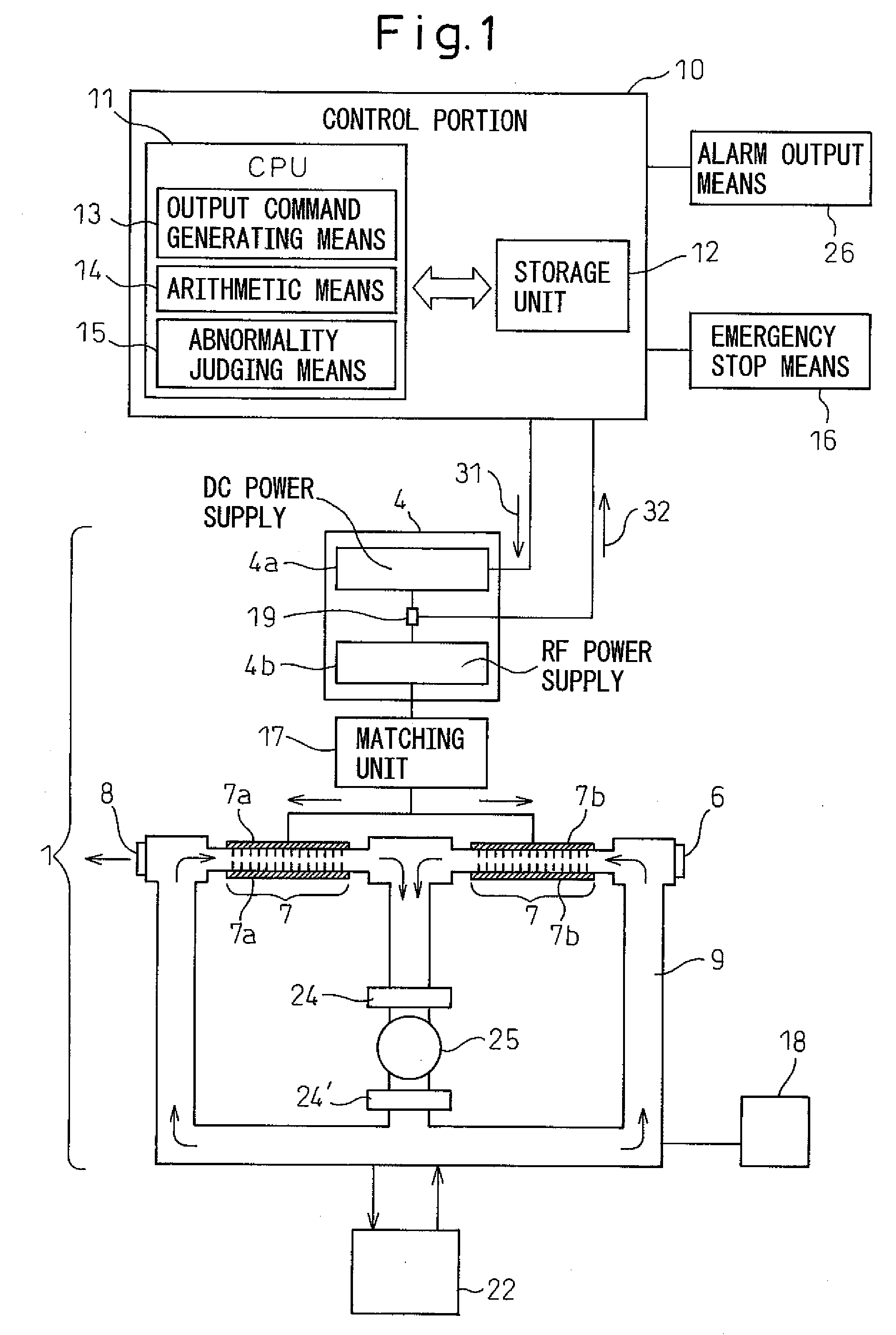
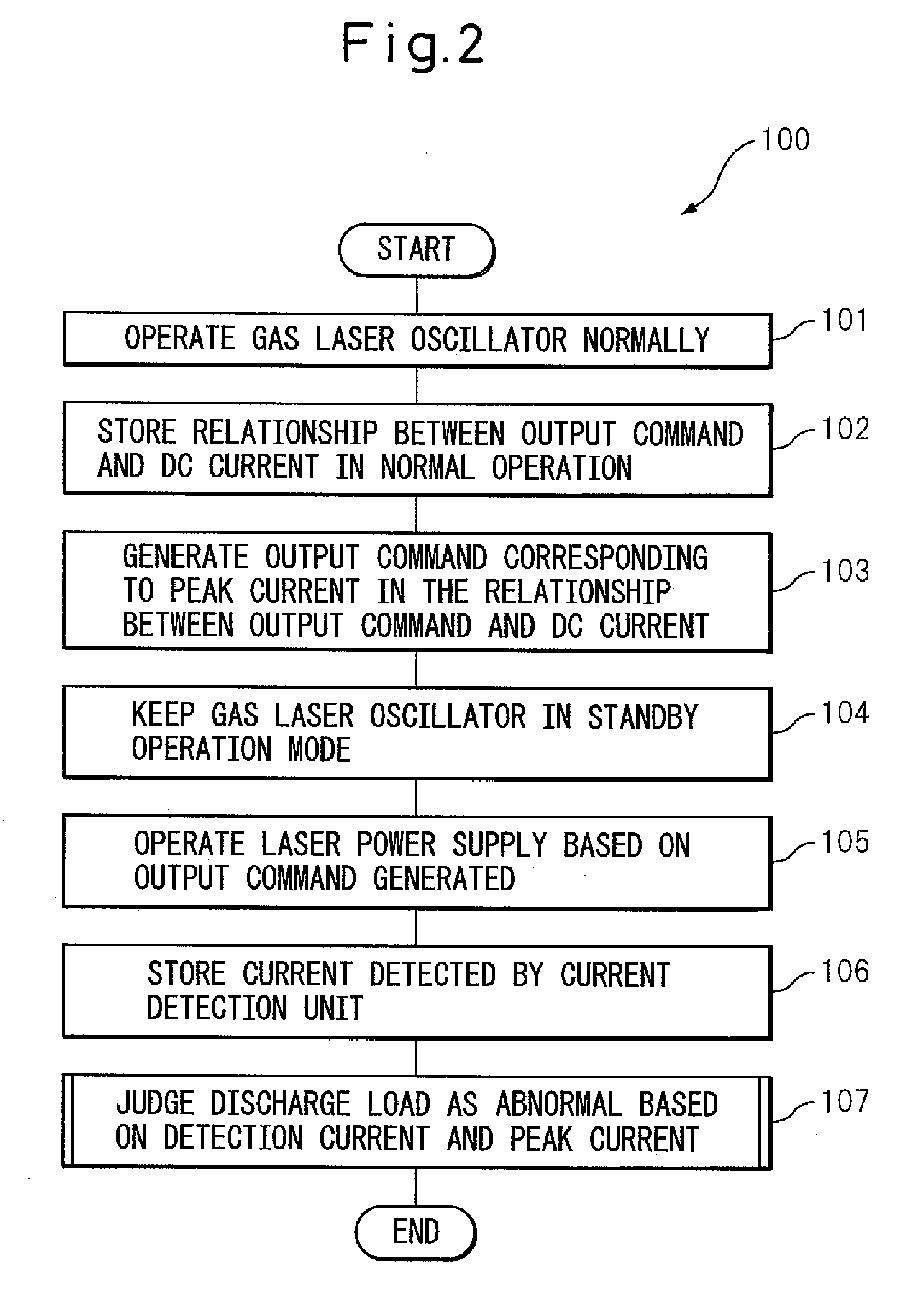
[0037]After that, in step 107, the abnormality judgment means 15 of the control portion 10 judges whether the discharge load is abnormal. FIG. 4a is a flowchart showing the abnormality judgment method according to the invention. As shown in step 201 of the operation program 200 in FIG. 4a, the arithmetic means 14 first calculates the difference ΔA (=Δ1−A0) between the detection current A1 and the peak current A0 in the relationship X0 between the output command and the DC current. Then, the abnormality judgment means 15 judges whether the difference ΔA is not less than a predetermined threshold value B1 or not. In the case where the difference ΔA is not less than the predetermined threshold value B1, in step 203, it is judged that the discharge load has an abnormality and ends the process. On the contrary, in the case where the difference ΔA is not less than the predetermined threshold value B1, the discharge load is not judged as abnormal.

second embodiment

[0038]In the abnormality judgment method shown in FIG. 4b, as shown in step 211 of the operation program 210, the arithmetic means 14 first multiplies the peak current A0 by a predetermined coefficient k (k>1. k=1.1 in FIG. 4b) to calculate a reference value A0′ (=k×A0). Then, the abnormality judgment means 15 judges whether the detection current A1 is not less than the reference value A0′. In the case where the detection current A1 is not less than the reference value A0′, in step 213, it is judged that the discharge load has an abnormality and ends the process. On the contrary, in the case where the detection current A1 is less than the reference value A0′, the discharge load is not judged as abnormal.

[0039]As described above, according to this invention, the discharge load is judged to have an abnormality in the case where the detection current A1 is larger than the peak current A0 by a threshold value B1 or larger than the reference value A0′ of the peak current A0. The reason ...


PUM


Abstract

A gas laser oscillator (1), which generates a laser beam by exciting laser gas in discharge tubes (7) with a laser power supply (4) and detecting an abnormality thereof, includes a storage unit (12) for storing the relationship between the output command and the DC current of the laser power supply (4) during the normal operation of the oscillator (1), an output command generating unit (13) for generating an output command corresponding to the peak current value in the relationship between the output command and the DC current, a current detection unit (19) for detecting the current during the operation of the laser power supply (4) based on the output command in the standby operation mode of the gas laser oscillator (1), and an abnormality judging unit (15) for judging that the discharge load of the gas laser oscillator (1) has an abnormality based on the detection current detected by the current detection unit (19) and the peak value of the current in the relationship between the output command and the DC current. In this way, the abnormality of the discharge load of the discharge tubes (7) can be easily and safely detected. The gas laser oscillator further desirably includes a stop unit for stopping the gas laser oscillator when the discharge load is judged as abnormal.

Description

BACKGROUND OF THE INVENTION[0001]1. Field of the Invention[0002]This invention relates to an abnormality detection method for detecting an abnormality of the discharge load of a gas laser oscillator and the gas laser oscillator for carrying out the method.[0003]2. Description of the Related Art[0004]A gas laser oscillator for producing laser output by exciting a gas is desirably operated with a normal, stable discharge load. For this purpose, a technique for determining and analyzing a laser gas composition in a discharge tube of a gas laser oscillator has been developed.[0005]Japanese Unexamined Patent Publication No. 7-221378 discloses a method in which the optimum matching between a laser power supply and a discharge load is obtained by combining the phases of a current and a high-frequency voltage for the discharge load. In Japanese Unexamined Patent Publication No. 7-221378, no peak current exists in the voltage-current relationship of the laser power supply, since the phases o...

Claims


Application Information

Patent Timeline
Patent Type & Authority Applications(United States)
IPC IPC(8): H01S3/22H01S3/00
CPCH01S3/09705H01S3/097
Inventor ANDO, MINORUIKEMOTO, HAJIME
Owner FANUC LTD
Why Eureka
Try Eureka