
Method and Device for Predicting a Life Expectancy of a Product Containing a Plurality of Components

a technology of plurality of components and life expectancy, which is applied in the direction of electrical controllers, program control, instruments, etc., can solve the problems of inability to run through the entire required minimum service life of the product, and inability to produce verification in real tim

Inactive Publication Date: 2009-05-07
ROBERT BOSCH GMBH
View PDF4 Cites 7 Cited by
  • Summary
  • Abstract
  • Description
  • Claims
  • Application Information

AI Technical Summary

Benefits of technology

The present invention provides a method and device for determining the reliability and service life of a product by simulating field conditions and analyzing the failure times of individual components. The method involves acting on the components of the product with different loadings until failure, and plotted the failure times of each component as a function of the load-dependent failure times. The resulting EOL curve of the product is determined and used to determine the durability of the product under the assumed field loading. The method allows for the rapid and accurate determination of the product's reliability and service life, and can also be used for reliability verification. The method is efficient and effective in identifying the components of the product that are most likely to fail and can also help prevent failures that are irrelevant to field conditions.

Problems solved by technology

If it fails prior to reaching the minimum service life, the verification is not able to be produced.
However, due to time restraints, it is usually impossible to run through the entire required minimum service life of the product (e.g., 15 to 20 years in the case of a motor-vehicle control unit) in real time, under the loadings occurring within the scope of its normal use or application.
However, the precise relationship between increased loading and shortened testing period is not known and may behave completely differently for different loadings and for different products.
Furthermore, this procedure results in an accumulation of errors that are a result of the increased loadings and, in reality, do not occur during normal operation or use of the product.
Such errors are also called errors irrelevant to field conditions.
That is to say, there is a conflict of goals between the shortening of the testing duration on the one hand and the effectiveness of the test results' simulation of field conditions on the other hand.
After the testing of a multitude of identical components, the conventional method provides statements, such as: “At absolute operating temperatures of above 90° C., there is a 97% probability of the product achieving a minimum service life of 5,000 hours of operation.” However, the conventional method cannot provide any statements beyond that.
This results from the view that a product fails in its entirety as soon as only one of the components breaks down.
In this case, at the predefined loading, the failure of the component thus occurs at a later time than the component must withstand at this loading according to the requirements of the verification.
At low loadings, in particular, a very long operating time of the component until failure may possibly result, i.e., the test duration may be very long.
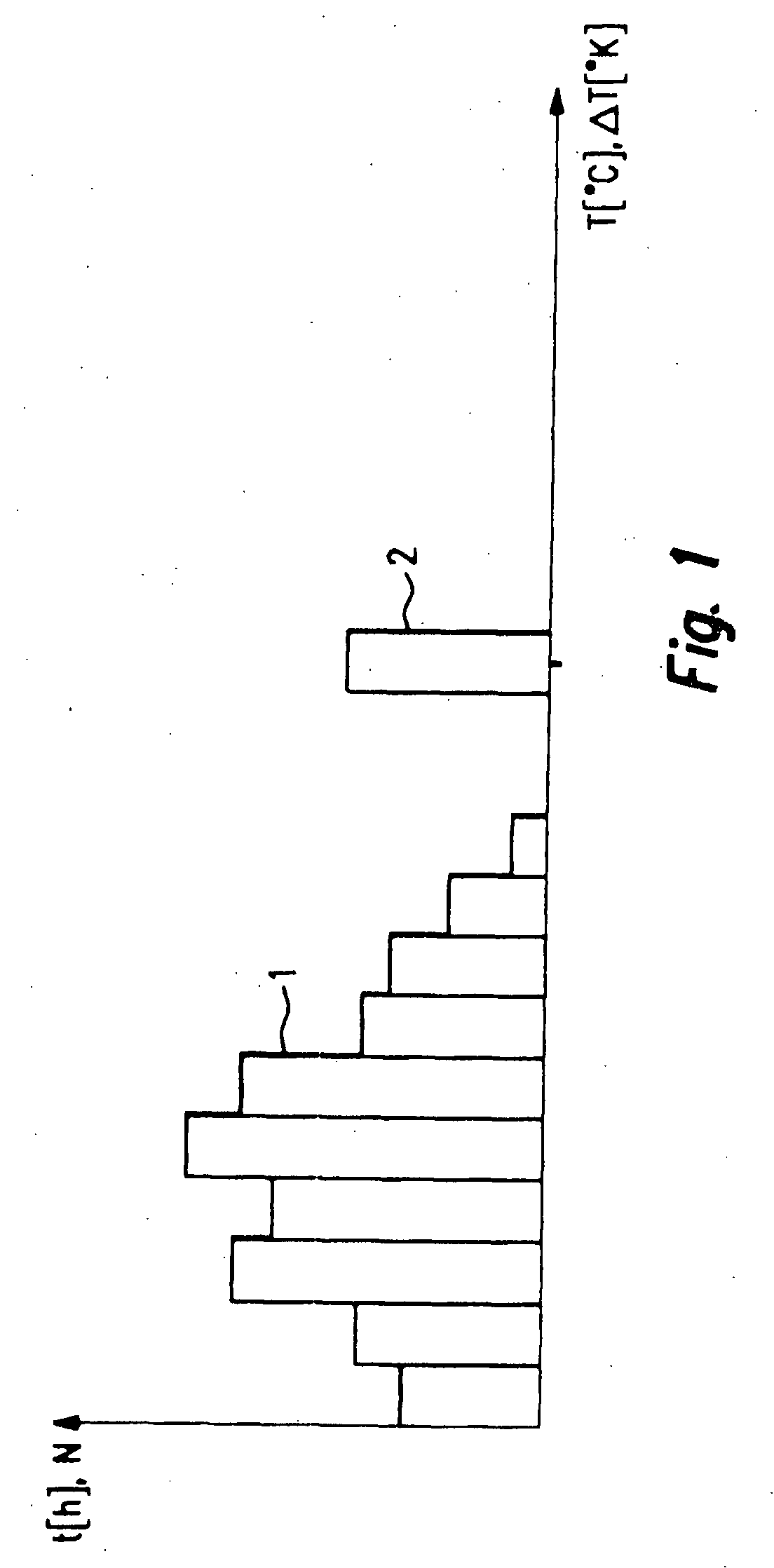
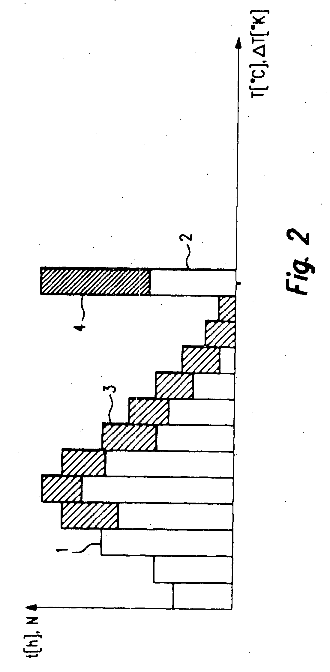
If, for example, the tested product is able to be operated for 150 hours in the first temperature class until failure, but only for 10 hours in the second class until failure, the product or a component of the product does not meet the customer's requirements.
Even if the product can be operated 25 hours in the second temperature class until failure, i.e., longer than specified by the customer, this may still result in the permissible loading of the product being exceeded overall, if it fails before reaching an exemplary, minimum service life of 180 hours required by the customer.
If the sum is greater than or equal to 1, premature failure of the component is to be expected.
For reasons of time, it is not possible to run through the actual loading profile in order to produce a reliability verification.
This produces load-dependent failure times for each component, which form the interpolation points of the EOL curve of the component.

Method used


Image

  • Method and Device for Predicting a Life Expectancy of a Product Containing a Plurality of Components
  • Method and Device for Predicting a Life Expectancy of a Product Containing a Plurality of Components
  • Method and Device for Predicting a Life Expectancy of a Product Containing a Plurality of Components

Examples


Embodiment Construction

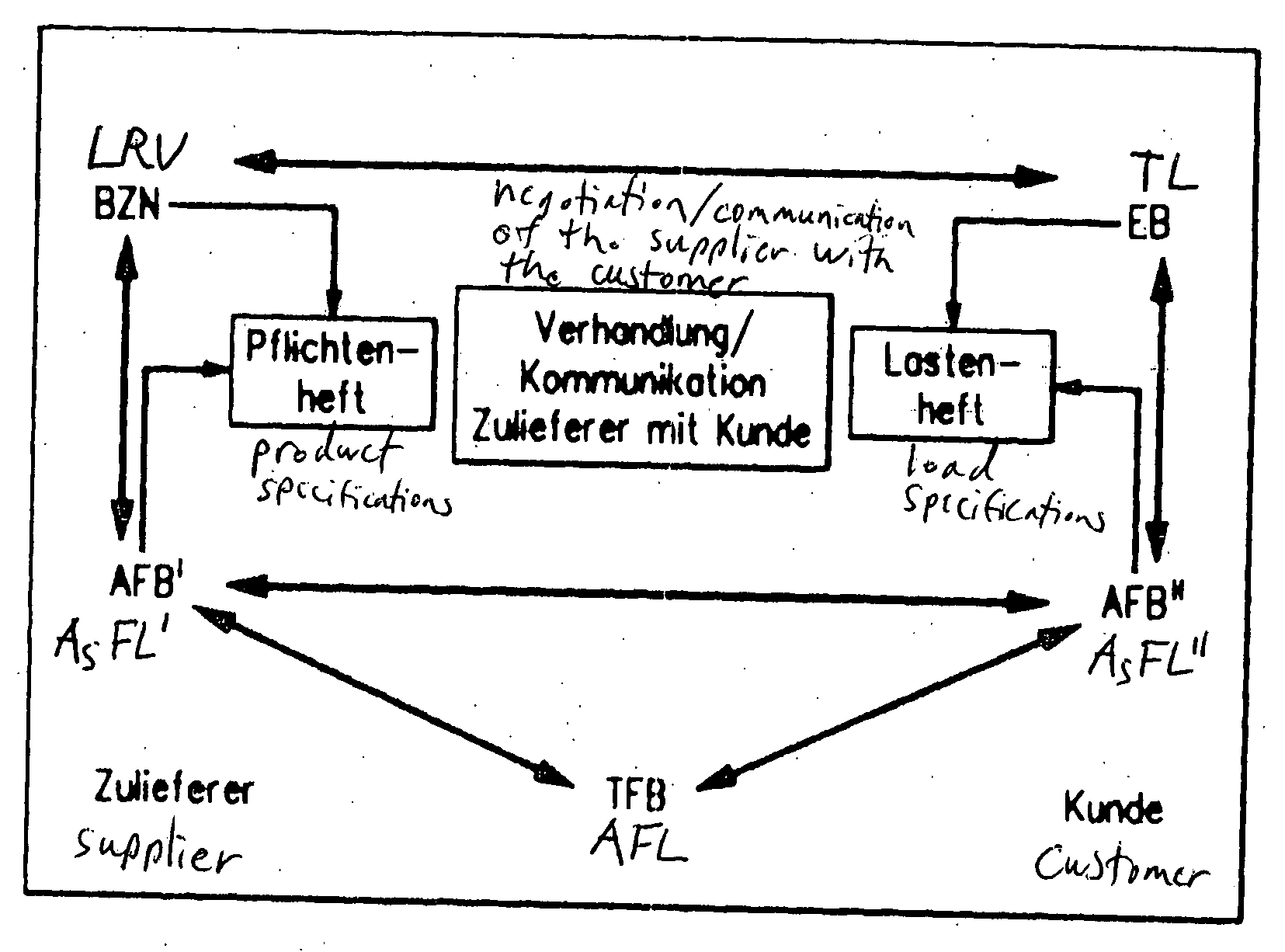
[0056]Conventionally, the testing of products or reliability verifications for products are implemented based on standards and standardized methods provided by customers or standardization committees. Described in these standards are accelerated tests that must be conducted on a product up to a specific operating time t or a specific number of cycles N, in order to be able to verify the reliability of the product. A test is referred to as accelerated tests, if it is carried out at higher loadings than the loadings that occur in the field, but only for a reduced time t or number of cycles N. The evaluation criterion for passing the reliability test is then generally the proof that the product functions after conclusion of the test. In this manner, a Yes or No assertion may be made as to whether or not the product withstands the required loading over the required period of time. However, an assertion regarding the service life of the product under an arbitrary loading cannot be made i...


PUM


Abstract

A method and a device are for predicting a life expectancy of a product, which includes at least two components. The life expectancy is ascertained as a function of an assumed field loading of the product. The components of the product are acted upon by different loadings and are operated, in each instance, at the different loadings until they fail. An end-of-life curve of the component is recorded on the basis of the load-dependent failure times of a component. An EOL curve of the product is ascertained such that at the different loadings, it includes the EOL curve of the components which has, in each instance, the shortest failure time at the corresponding loading. The anticipated service life of the product is determined as a functional value of the EOL curve of the product as a function of the predefined loading of the product.

Description

FIELD OF THE INVENTION[0001]The present invention relates to a method and a device for predicting a life expectancy of a product, which includes at least two components. The life expectancy is determined as a function of a predefinable loading of the product.[0002]The present invention also relates to a computer program, which is executable on a computing element, in particular on a microprocessor, of a data-processing system.BACKGROUND INFORMATION[0003]In different technical fields, products are employed or utilized that have a specific service life as a function of the loading to which they are subjected to during their operation. A product encompasses a plurality of components. A product may be a personal computer (PC), the components then being the electrical components (power supply, main board, hard disk, disk drive, CD-ROM drive, DVD drive, etc.) of the PC. It would also be POSSIBLE, for example, to regard the main board as the product, the different electrical components, so...

Claims


Application Information

Patent Timeline
Patent Type & Authority Applications(United States)
IPC IPC(8): G06F19/00
CPCG05B2219/37253G05B19/4065
Inventor VOIGTLAENDER, KLAUSDUERR, JOHANNESBECKER, ROLFMUENCH, REINHOLDDURDEVIC, IVICAWOSTRADOWSKI, UWEHAHN, CHRISTOPHERBREIBACH, JOERGJAECKLE, PHILIPPEEHRHARDT, HENDRIKRUPP, THOMASCHABAUD, ANTOINE
Owner ROBERT BOSCH GMBH
Learn More