Method of operation for an electromechanical actuator for an awning with arms

an electromechanical actuator and awning technology, applied in the direction of sunshades, ac motor stoppers, building components, etc., can solve the problems of complex technology, rarely, or even never, used in the field of automated solar protection, and disturb the counting of positions, so as to avoid damage to the installation and low detection thresholds

Active Publication Date: 2009-05-14
SOMFY ACTIVITES SA
View PDF10 Cites 2 Cited by
  • Summary
  • Abstract
  • Description
  • Claims
  • Application Information

AI Technical Summary

Benefits of technology

[0023]The aim of the invention is to provide a method of operating an actuator that solves the above mentioned problems and improves the methods of operation known from the prior art. In particular, when resetting is necessary, the invention allows prior determination in an overall manner of the position of the awning in order to authorize an automatic position reset without intervention by the user and without error. It also enables the use of fairly low detection thresholds so as not to damage the installation when detecting the stop.

Problems solved by technology

Adjustment of such an electronic counting device may be carried out at a distance, which obviously has many advantages, as the actuators are not easily accessible once fitted on site.
However, if such actuators with an electronic counting device are equipped with a manual emergency control, a manual movement carried out during a power outage may disturb the position counting: the awning is indeed moved without the electronic counting system changing the value of the current position.
It is also unlikely that the awning will return to its initial position after this manual operation.
This situation can be avoided by using absolute position sensors, but these are made of complex technology and rarely, or even never, used in the field of automated solar protection.
Each micro-power outage may lead to a resetting.
However, this solution requires the employment of new counting means apart from the existing means or adapted counting means, which further increases the price of devices with emergency operation.
The use of this system for a garage door requires the fitting of passpoint sensors or zone indicators distinguishing the operational zones, which increases the cost of the system.
However, this method can be applied only if the position is known reliably, i.e. it is not suitable in the previously presented case in which the installation is not properly adjusted following a manual operation.

Method used


Image

  • Method of operation for an electromechanical actuator for an awning with arms
  • Method of operation for an electromechanical actuator for an awning with arms
  • Method of operation for an electromechanical actuator for an awning with arms

Examples


Embodiment Construction

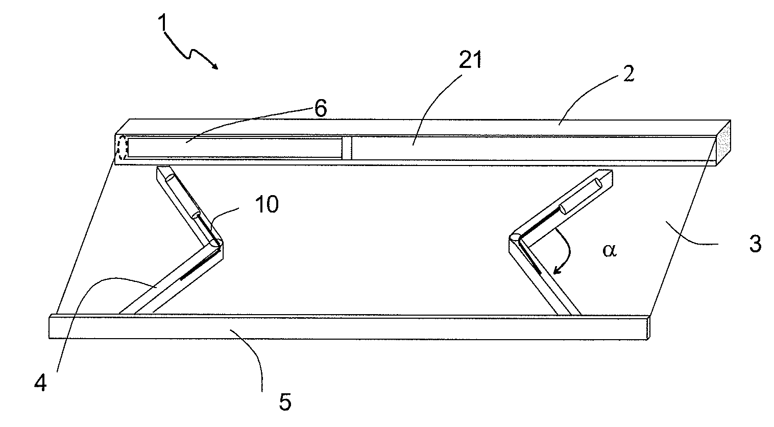
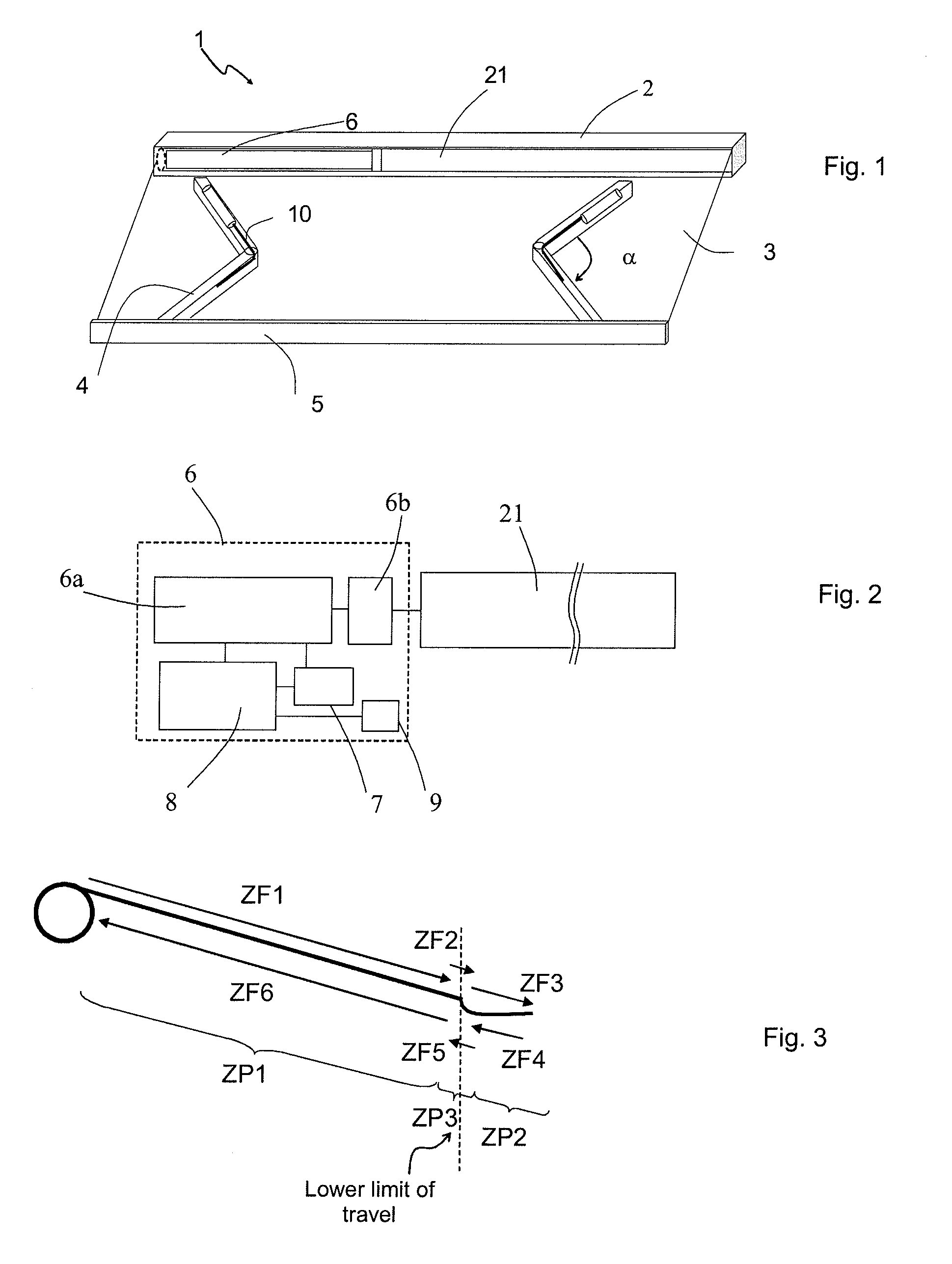
[0032]The solar protection installation 1, in particular a motorized awning with arms, comprises a roller tube 21 around which an awning fabric 3 is wound in a box 2. The installation also comprises hinged arms 4 mounted on one side on a bearing structure and equipped with springs 10 that are stretched when the arms are retracted. The other end of the arms is connected to a bar 5 fixed at the bottom of the fabric 3. A tubular actuator 6 inserted inside the roller tube 21 (or drive tube) causes the latter to rotate. The actuator comprises a control unit 8 allowing it to manage control commands to extend or retract the fabric. When there is a command to extend, the actuator permits an extension of the arms under the action of the springs and a rotation of the roller tube in a first direction, which leads to extension of the fabric. Conversely, when there is a command to retract, the actuator causes rotation of the roller tube in the opposite direction, which has the effect of tighteni...


PUM


Abstract

A method of operating an electromechanical actuator (6) for an awning with arms (1), comprising a control unit (8), stop detection means (9) and means (7) for measuring a parameter (Ucapa) of the actuator, the awning being able to move over its travel in at least a first (ZP1) and a second (ZP2, ZP3) positioning zone, the method comprising the following steps:upon detecting an initiating event, automatic determination, from the measurement of the parameter of the actuator, of the positioning zone in which the current position of the awning is located; andif the current position of the awning is located in the second positioning zone, temporary deactivation of the stop detection means for detecting a stop in the course of a movement of the awning towards a stop position.

Description

[0001]The invention relates to the field of automated solar protection, in particularly awnings driven by an actuator.BACKGROUND OF THE INVENTION[0002]A fabric forming the awning is designed to be wound onto a tube called the roller tube, the rotation of the latter being produced either by means of an electromechanical actuator or thanks to a manual operation device or a handle.[0003]Tubular actuators are very commonly used for these automatic operations. They are located inside the roller tube and enable the fabric of the awning to be unwound or wound without particular effort. In addition, associated with automation or sensors, the operation of the awning may be remotely carried out, without the need for user intervention (for example, automatic unwinding in the presence of sun to protect both the terrace or the windows from too much heating in summer, automatic winding in the event of wind to protect the awning itself).[0004]Electromechanical actuators are generally connected to ...

Claims


Application Information

Patent Timeline
Patent Type & Authority Applications(United States)
IPC IPC(8): E04F10/00
CPCE04F10/0618E04F10/0659E05Y2400/34E05Y2900/146E05F15/40E06B2009/6854E06B2009/6872E05Y2800/00E06B2009/6845E05Y2900/00
Inventor GERMAIN, FLORIANLOZANO, PHILIPPEMUGNIER, DAVID
Owner SOMFY ACTIVITES SA
Why Eureka
Try Eureka