
Length adjustable support

a technology of adjustable support and adjustable height, which is applied in the direction of adjustable height tables, tables, domestic objects, etc., can solve the problems of easy wear and tear of elastic extension supports, limited support, and complicated operation of elastic extension supports

Inactive Publication Date: 2009-05-14
VEYHL
View PDF8 Cites 12 Cited by
  • Summary
  • Abstract
  • Description
  • Claims
  • Application Information

AI Technical Summary

Benefits of technology

[0013]A rotatability of the support column within the tube profile can be prevented in the support according to the invention by mounting parts which are in supporting engagement with another, e.g. a tabletop with respect to the floor, which do not rotate with respect to each other, i.e. rotation-resistant. In the case of a tabletop, this is already the case when there are several table legs provided to support the tabletop.
[0014]The locking according to the invention of the rotary motion of the motion thread of the spindle rod for height adjustment of the support, i.e. for locking the extended position of the guide column, allows for simple and reliable length adjustment of the support. The length adjustment mechanism formed by the spindle rod with a motion thread and the support column is virtually wear-free and very robust. Elastic facilitations of extension which impede slipping through are replaced by the fact that the screwing-in and unscrewing, respectively, of the spindle rod into / out of the support column of the support, which is required for length adjustment of the support according to the invention, impedes an insertion of the support column into the tube profile. For the case of use of the support according to the invention as, for example, a table leg, this slows down a slipping through to the bottom.
[0016]Particularly advantageously, the locking means have an elastic element mounted in a rotation-resistant manner in the tube profile, which can be elastically deformed by activating a trigger, preferably protruding out of the tube profile, in such a way that, due to be elastic deformation of the element, the pin can be unlatched from the indentation for releasing the rotatability of the spindle rod in the tube profile. The length and height, respectively, of the support according to the invention can thereby be set via a simple elastic deformation of the locking means and without any tools. Thus, for example, the height adjustment of a table with table legs comprising a support according to the invention can easily be accomplished by one person only.
[0019]Particularly advantageously, the locking means have a bore through which the spindle rod is guided and a locking ring which prevents a pushing-out of the spindle rod from the bore at the free end of the end area of the spindle rod. The spindle-side end of the end area on the spindle rod provides a supporting edge which blocks a pushing-in of the spindle rod into the bore. Thus, a simple and robust securing of the spindle rod against axial displacement relative to the tube profile can be achieved. If a sliding washer is provided between the supporting edge and the locking means, the friction between the spindle rod and the locking means is minimized so that the free movement of the screwing motion of the spindle rod when pulling in and / or out the support according to the invention is improved.
[0023]The rotation-resistant guide of the support column in the tube profile can be easily achieved via a rotation-resistant guide of the inner profile in the outer profile and a rotation-resistant fixing of the outer profile to the support column.
[0025]The pin(s) of the ring element can thereby be designed such that, in the case of pressure load being applied on a tabletop, it or they wedge more severely in one or several indentations of the locking disk, thus additionally securing the selected height adjustment of the length-adjustable support.

Problems solved by technology

The known supports, in particular, in the mounted state, e.g. those of a table, are often characterized by their adaptation mechanism and their operation is partly quite complicated.
Due to their design, the elastic facilitations of extension are susceptible to wear and provide only limited support.

Method used


Image

  • Length adjustable support
  • Length adjustable support
  • Length adjustable support

Examples


Embodiment Construction

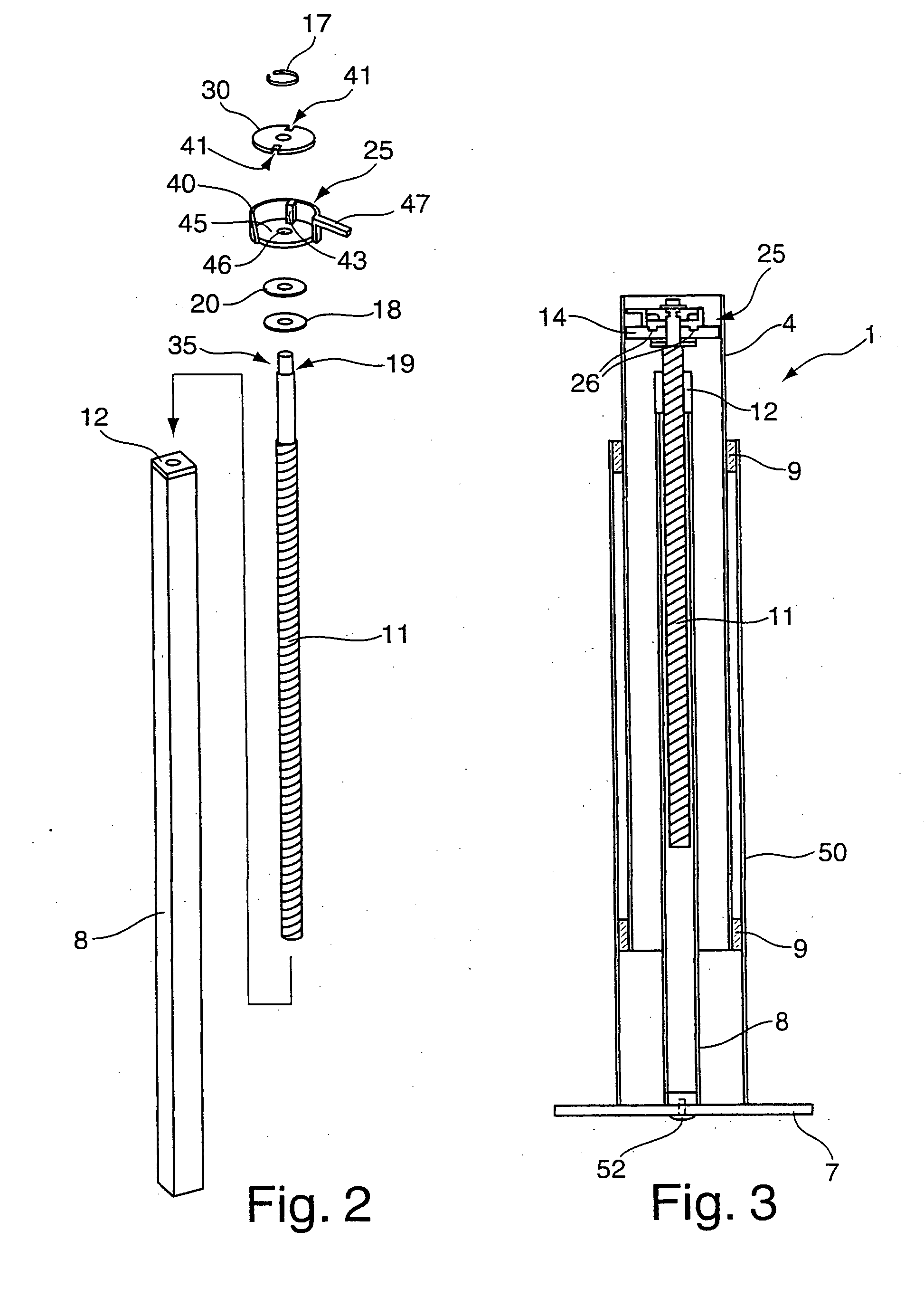
[0030]The figures of the drawings show the object according to the invention strongly schematized and are not to be taken to scale. The individual components of the object according to the invention are represented such that their design can be easily seen.

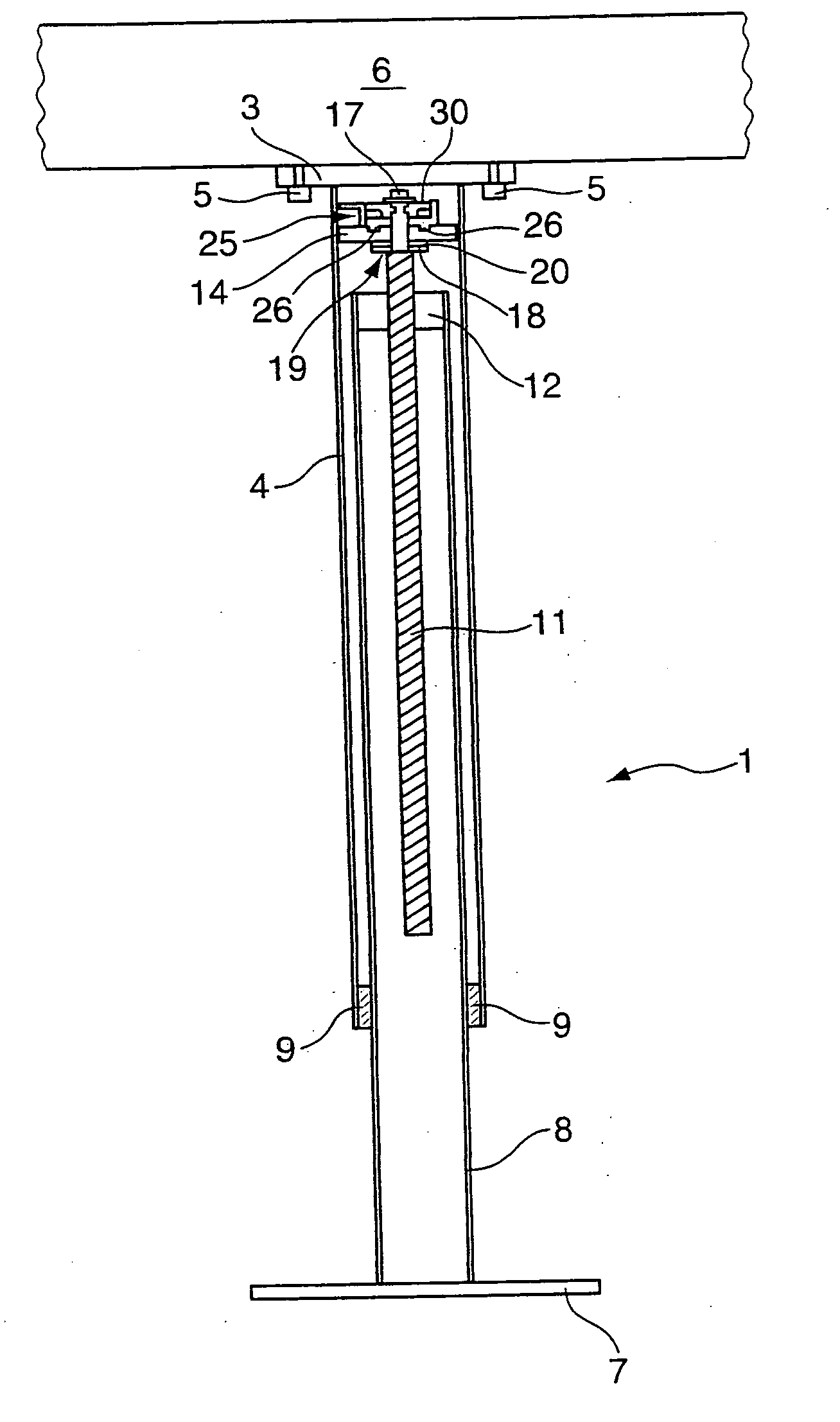
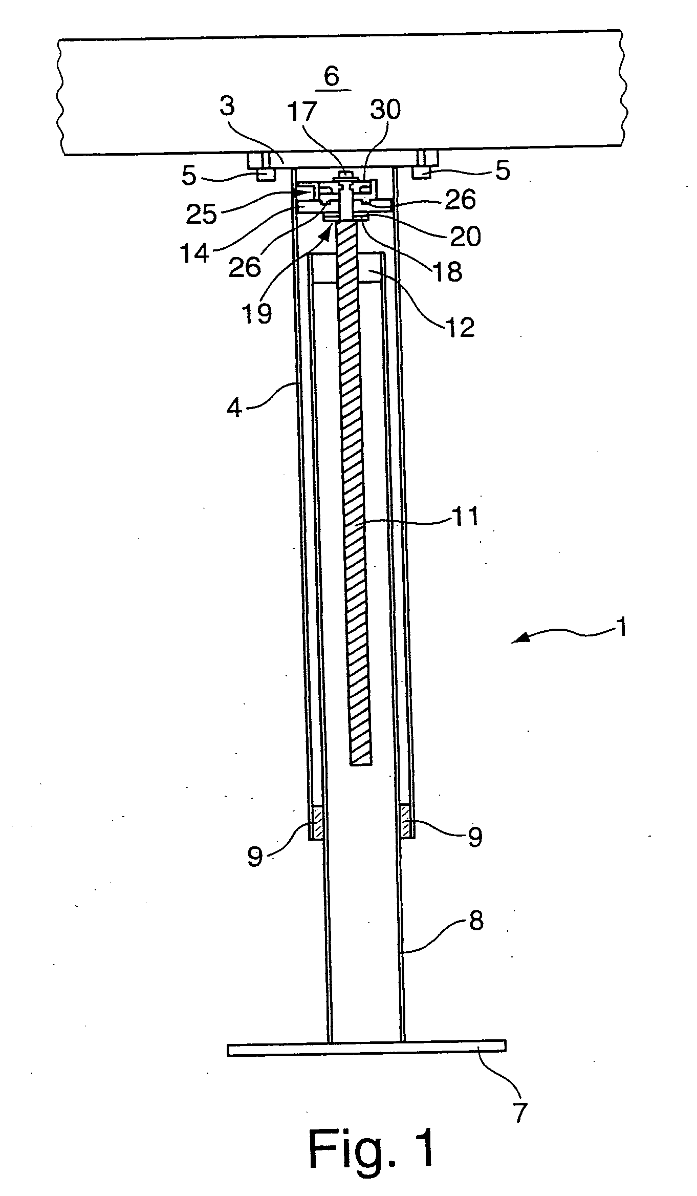
[0031]FIG. 1 shows a support 1 according to the invention designed as a table leg. The support 1 has a fixing plate 3 at its upper end, being fixed to the free upper end of the tube profile 4 of the support 1. The fixing plate 3 is mounted to a tabletop 6 via screws 5. A ground plate 7 is provided at the lower end of the support 1 by means of which the support 1 or the table leg stands on the floor when the table is mounted. The ground plate 7 is mounted to the free lower end of a support column 8 of the support 1.

[0032]The support column 8 is telescopic and guided in the tube profile 4 via sliding guides 9. Among numerous other guide options, the support column 8 can alternatively also be guided in the tube profile 4 via a rollin...


PUM


Abstract

Proposed is a length-adjustable, in particular, height-adjustable support 1 with a tube profile 4 preferably designed as cylinder profile, a telescopic support column 8 guided in the tube profile 4, and a spindle rod 11 which is guided in the support column 8 via a motion thread and mounted in a rotatable manner in the tube profile 4 in a free end area of the spindle rod 11, projecting out of the support column 8, and secured against axial displacement relative to the tube profile 4 via locking means. Locking means 25 are designed to block the radial rotatability of the spindle rod relative to the tube profile 4.

Description

[0001]This application claims Paris Convention priority of DE 10 2007 054 192.0 filed Nov. 14, 2007 the complete disclosure of which is hereby incorporated by referenceBACKGROUND OF THE INVENTION[0002]The invention relates to a length-adjustable, in particular, a height-adjustable support with a tube profile and a telescopic support column guided inside the tube profile.[0003]Pieces of furniture such as tables or office chairs must often be adjustable in height, e.g. the tabletop or seating surface. Towards this end, the table legs can, for example, be designed in a length-adjustable manner as telescopic supports. Locking means are provided for fixing the extended position of the support column and thereby the height of the support and to secure the support column with respect to the tube profile at its longitudinal extension in a set, extended position. For example, a splint is often inserted in bores provided along the longitudinal extension of the support.[0004]It is furthermore ...

Claims


Application Information

Patent Timeline
Patent Type & Authority Applications(United States)
IPC IPC(8): F16M11/26A47B91/02
CPCA47B9/04
Inventor WAIDELICH, WERNERSCHOBER, HORST
Owner VEYHL
Learn More