Vor monitoring receiving apparatus and vor monitor receiving method
- Summary
- Abstract
- Description
- Claims
- Application Information
AI Technical Summary
Benefits of technology
Problems solved by technology
Method used
Image

Examples
Embodiment Construction
[0019]An embodiment of the invention will be described in detail with reference to the accompanying drawings.
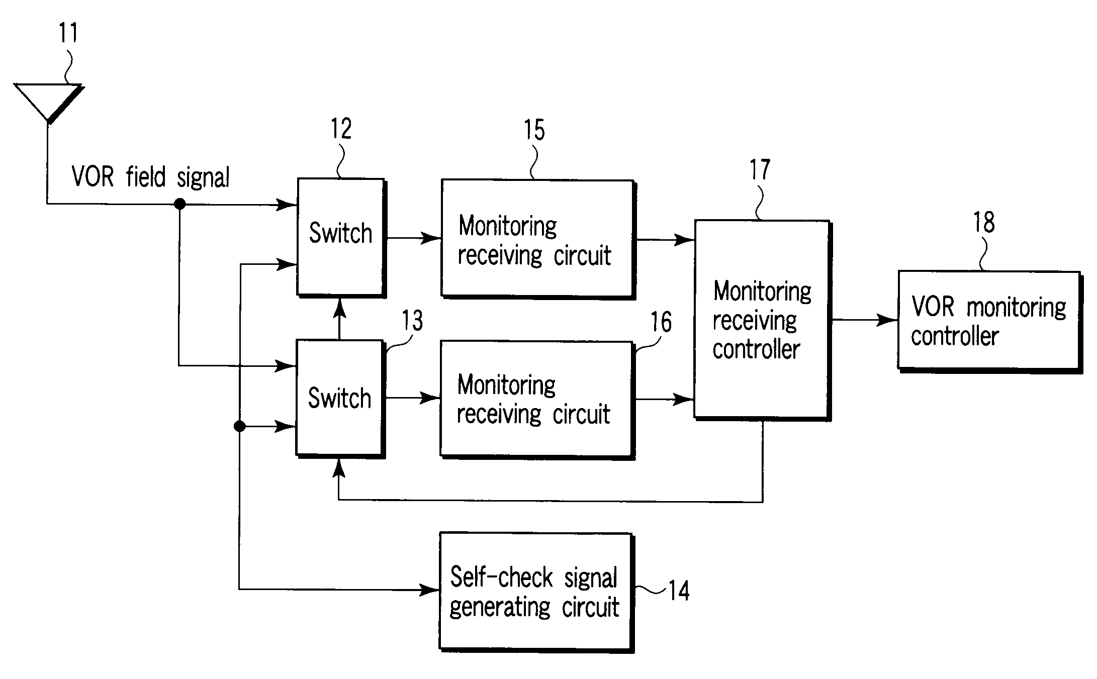
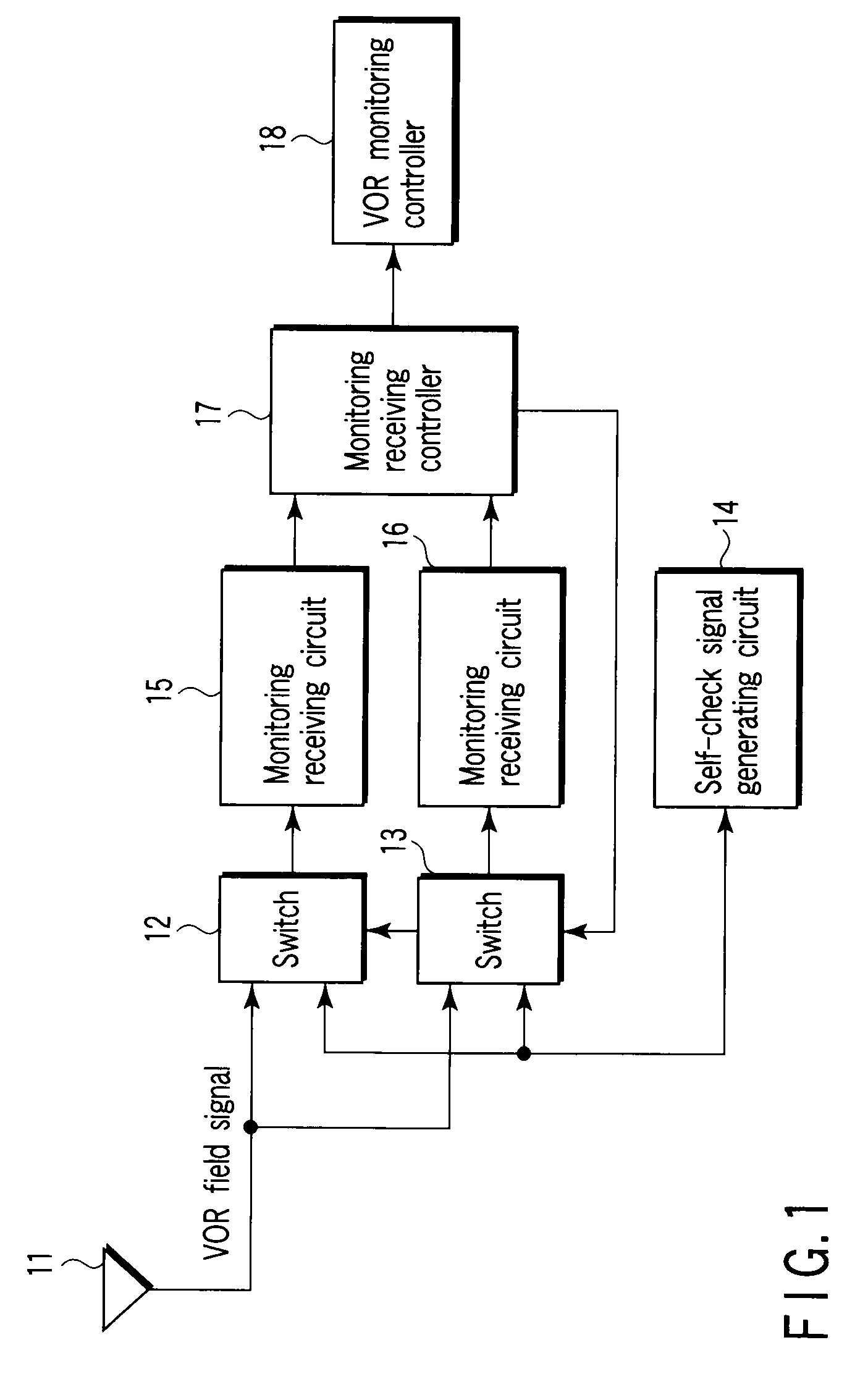
[0020]FIG. 1 is a block diagram illustrating the configuration of a VOR monitoring receiving apparatus according to an embodiment of the invention.
[0021]In FIG. 1, a VOR field signal output from a VOR apparatus (not shown) and received by a monitor receiving antenna 11, and a self-check signal generated by a self-check signal generation circuit 14 are selectively supplied to first and second monitoring receiving circuits 15 and 16 via first and second switches 12 and 13, respectively. The monitor output results of the first and second monitoring receiving circuits 15 and 16 are supplied to a VOR monitor controller 18 via a monitoring receiving controller 17, where abnormality detection of the VOR apparatus is executed.
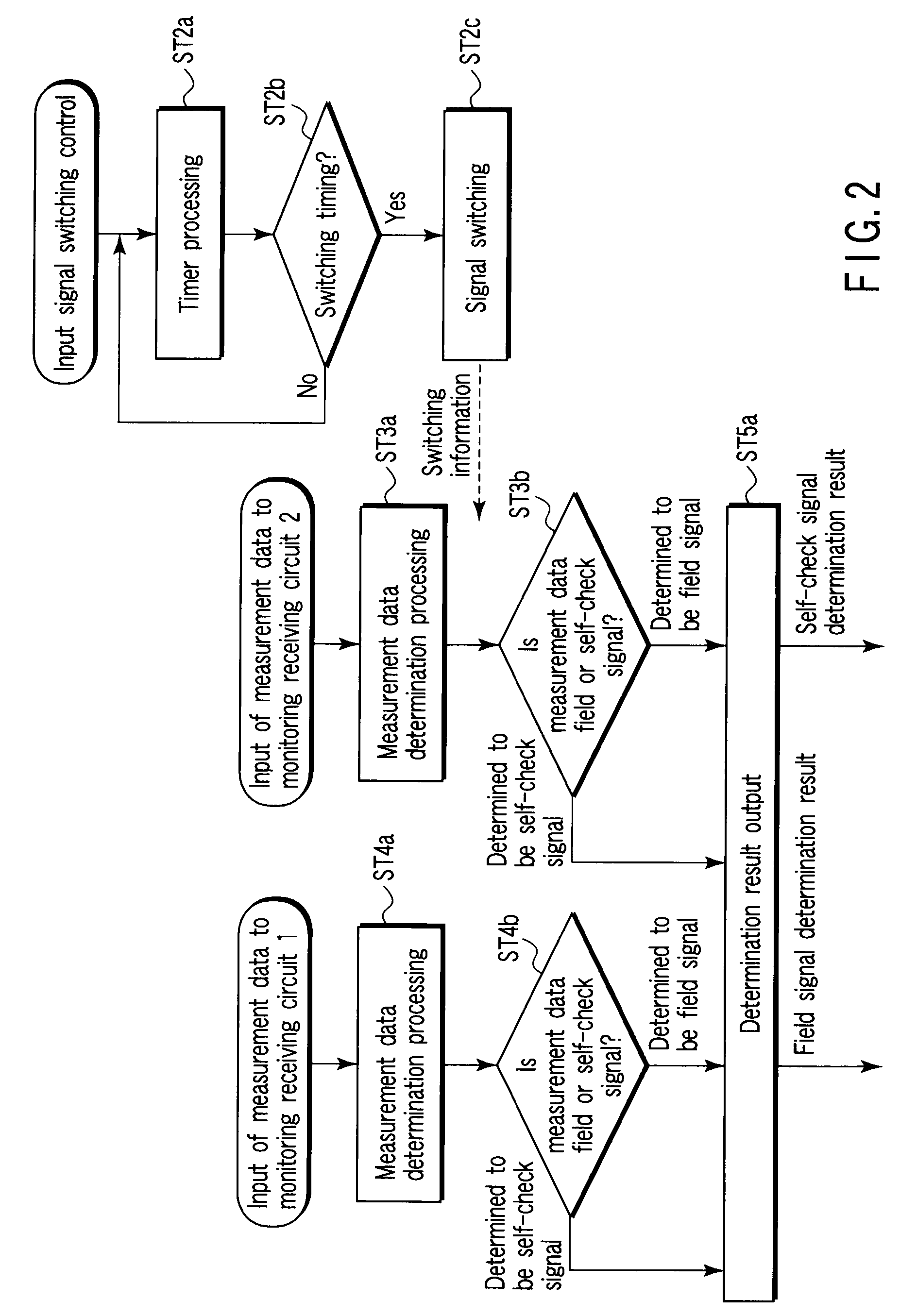
[0022]The operation of the above-mentioned structure will now be described. FIG. 2 is a flowchart illustrating the procedure of processes performed by the VOR m...
PUM
 Abstract
Description
Claims
Application Information
 - R&D
- Intellectual Property
- Life Sciences
- Materials
- Tech Scout
- Unparalleled Data Quality
- Higher Quality Content
- 60% Fewer Hallucinations
Browse by: Latest US Patents, China's latest patents, Technical Efficacy Thesaurus, Application Domain, Technology Topic, Popular Technical Reports.
© 2025 PatSnap. All rights reserved.Legal|Privacy policy|Modern Slavery Act Transparency Statement|Sitemap|About US| Contact US: help@patsnap.com