Method for detecting events at a secured location

a technology for detecting events and secure locations, applied in television systems, alarms with smoke/gas/colored powder, instruments, etc., can solve the problems of lack of ability to distinguish between false detection and actual alarm conditions, lack of ability to learn to distinguish between false detection and actual alarm conditions, lack of ability to deter trespassing, theft,

Inactive Publication Date: 2009-05-14
LATHAM JOEL PAT +5
View PDF25 Cites 35 Cited by
  • Summary
  • Abstract
  • Description
  • Claims
  • Application Information

AI Technical Summary

Benefits of technology

[0014]In another aspect, the present invention provides a security system for monitoring an area and having a security detection system local to the monitoring area for detecting a security event, the security detection system including a visual detection device for detecting a security event and, responsive to detecting a security event, generating data indicative of the security event, a deter device, and an input / output communication device coupled with the security detection system and the deter device for transceiving data, security system including an operator for supervising the monitored area, and a wireless communication system for transceiving the generated data received from the input / output communication device to the operator, wherein the operator can determine if the deter device is to be actuated based on the generated data, and wherein the operator can be onsite to the monitored area and can be remote to the monitored area.

Problems solved by technology

Such systems and methods may also include backup battery protection and remote paging capabilities, but all lack to ability to use sensors to distinguish and / or learn to distinguish between a false detection and an actual alarm condition.
They also lack sufficient ability to deter trespassing, theft, and / or sabotage by individuals.

Method used


Image

  • Method for detecting events at a secured location
  • Method for detecting events at a secured location
  • Method for detecting events at a secured location

Examples


Embodiment Construction

[0023]Whether involved in site preparation, drilling, extraction, or cleanup, a company's financial commitment is immense. Each step represents an investment of hundreds of thousands, if not millions of dollars—an investment worth protecting. The present invention is an advanced system which can be self-contained, self-powered analytics system that protects investments.

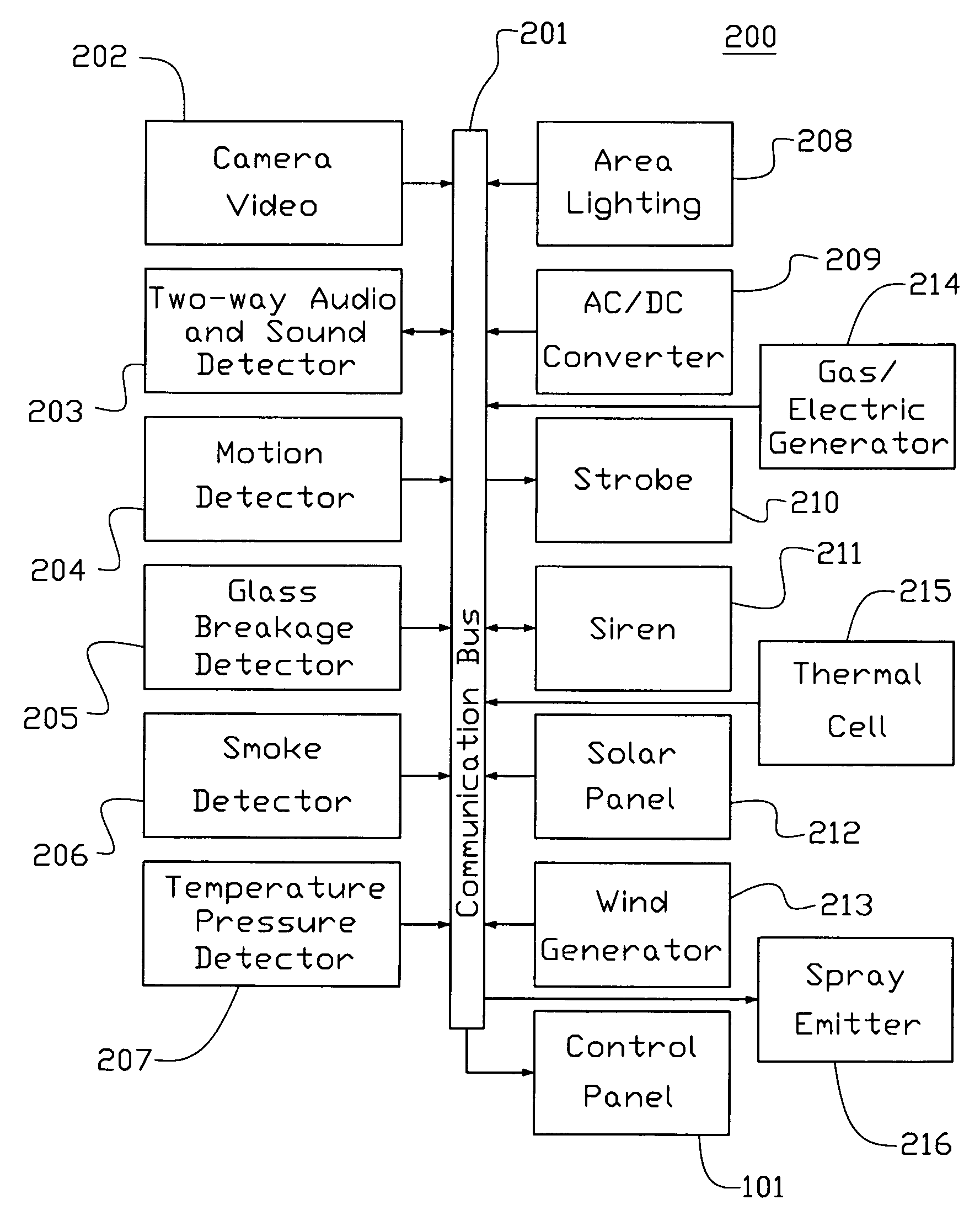
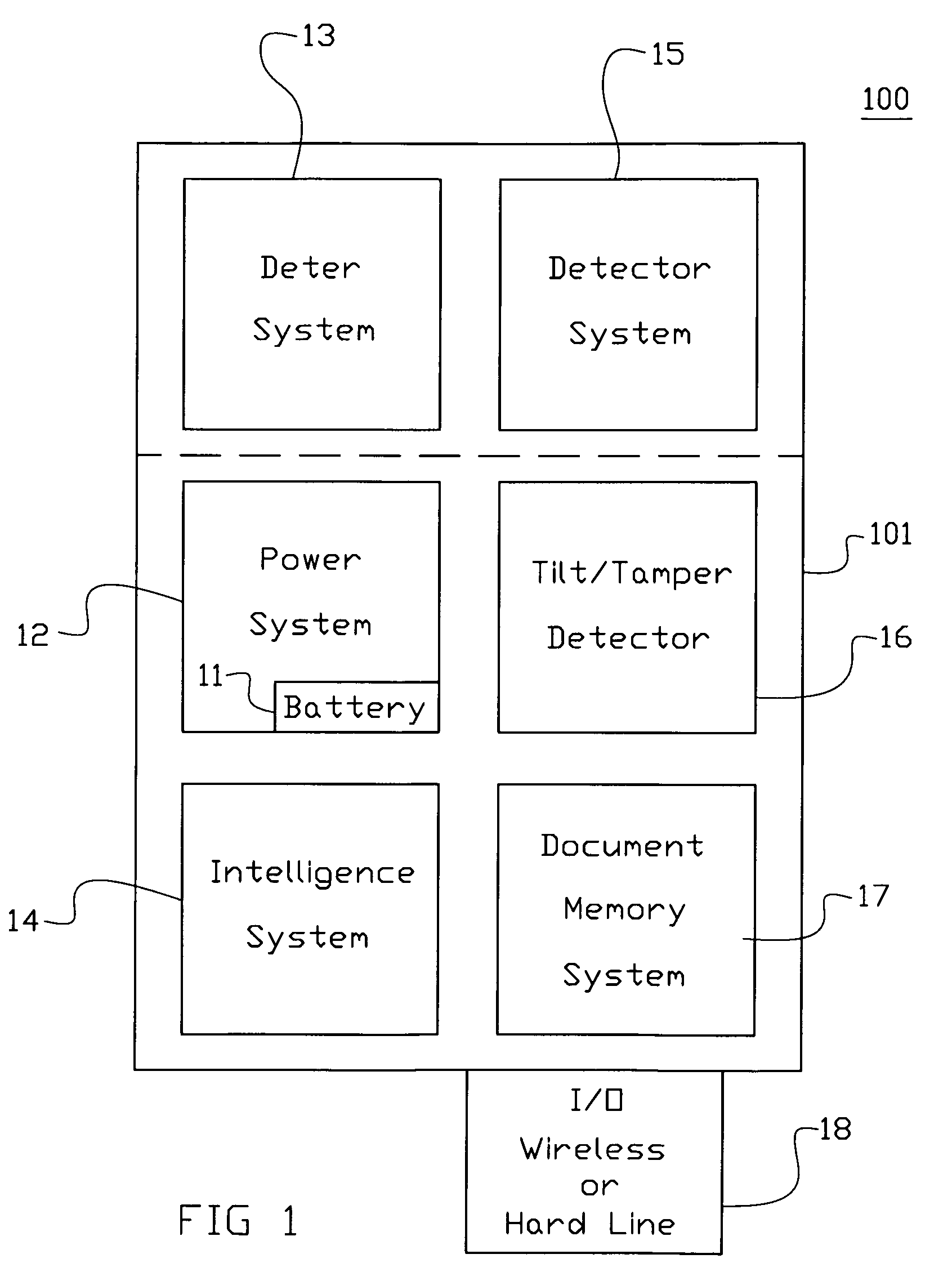
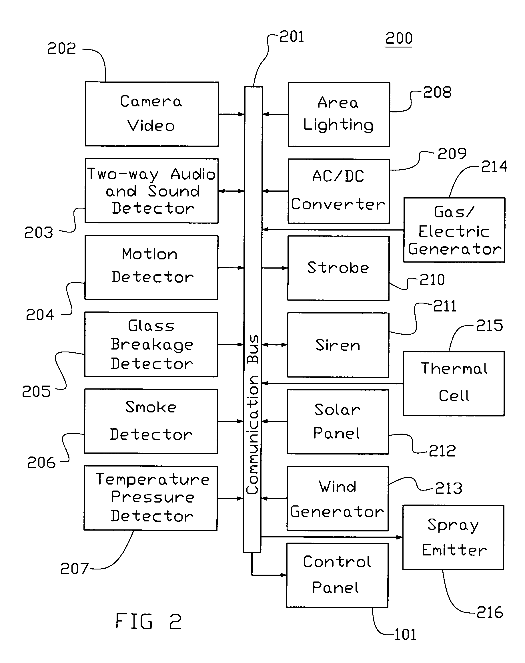
[0024]The present invention offers real-time event detection. One can monitor the exact location of choice—large or small—and can designate specific activities to detect. Once designated, the specific area to be monitored, the present invention's video / cameras can capture activity occurring in the monitored area. These images are transferred to the present invention's Intelligence system (IS) 14 for real-time analysis and the IC can define what constitutes a security event for the location being monitored. So whether concerned about intruders, theft, sabotage, or unusual changes in the area monitored, the present inve...


PUM


Abstract

A method for detecting events/activities at a secured location in which the security method may include an operator and/or determination application for supervising the location, and a transmission network for transceiving data indicative of determined activities of the secured location, wherein the determination application and the operator can initiate a deter device in response to adverse activities. The determination application of the security method may include an intelligence system for distinguishing between normal and adverse conditions. The method may also include an application for the transfer of activity data to a storage device in which operator(s) may access the stored data.

Description

CROSS REFERENCE TO RELATED APPLICATIONS[0001]This application is related to two copending applications filed on the same day as the present application, the contents of both being incorporated herein by reference. One is entitled, “A Detecting, Detering Security System”, Ser. No. ______, and assigned to the same assignee as the present application. The second related application entitled, “A Security System and Network”, Ser. No. ______, and also assigned to the same assignee as the present applicationTECHNICAL FIELD[0002]The present invention relates to security methods and, more specifically, security methods for use in securing defined locations.BACKGROUND OF THE INVENTION[0003]Security systems are known in the art and a typical security system is located for the purpose of securing a defined area and discouraging unwanted and illegal activities such as trespassing, theft, sabotage. The defined area that is secured by the security system will usually comprise a closed area, such ...

Claims


Application Information

Patent Timeline
Patent Type & Authority Applications(United States)
IPC IPC(8): H04N7/18
CPCG08B13/19632G08B15/02G08B13/19697
Inventor LATHAM, JOEL PATBELDEN, STEVEN WAYNELATHAM, GREIG STOVALLHALL, BARRY ARTHURRAMSEY, MICHAEL A.KYLE, MATT
Owner LATHAM JOEL PAT
Why Eureka
Try Eureka