
Methods for geomechanical fracture modeling

a geomechanical and fracture modeling technology, applied in the field of geomechanical fracture modeling, can solve the problems of large fracturing treatment of vertical wells, low productivity, premature termination of fracturing process,

Inactive Publication Date: 2009-05-14
HALLIBURTON ENERGY SERVICES INC
View PDF9 Cites 83 Cited by
  • Summary
  • Abstract
  • Description
  • Claims
  • Application Information

AI Technical Summary

Benefits of technology

The present invention relates to methods for designing and optimizing the number, placement, and size of fractures in a subterranean formation. The invention takes into account stress interference from other fractures to improve the overall design and optimization. The invention includes steps of determining geomechanical stresses induced by each fracture, determining a geomechanical maximum number of fractures, predicting a predicted stress field, and predicting a predicted surface deformation caused by each fracture. The invention also includes a computer program for optimizing the number, placement, and size of fractures in a subterranean formation. The technical effects of the invention include improving the overall design and optimization of fractures in a subterranean formation, reducing stress interference, and optimizing surface deformation.

Problems solved by technology

2. low productivity due to low formation permeability;
In the fourth case, a large fracturing treatment of a vertical well would not be an acceptable option since the fracture would grow in height as well as length.
In some circumstances, however, the fracturing process may terminate prematurely, for a variety of reasons.
For example, the “pad” portion of the fracturing fluid, which is intended to advance ahead of the proppant as the fracture progresses, may undesirably completely “leak off” into the formation, which may cause the proppant to reach the fracture tip and create an undesirable “screenout” condition.
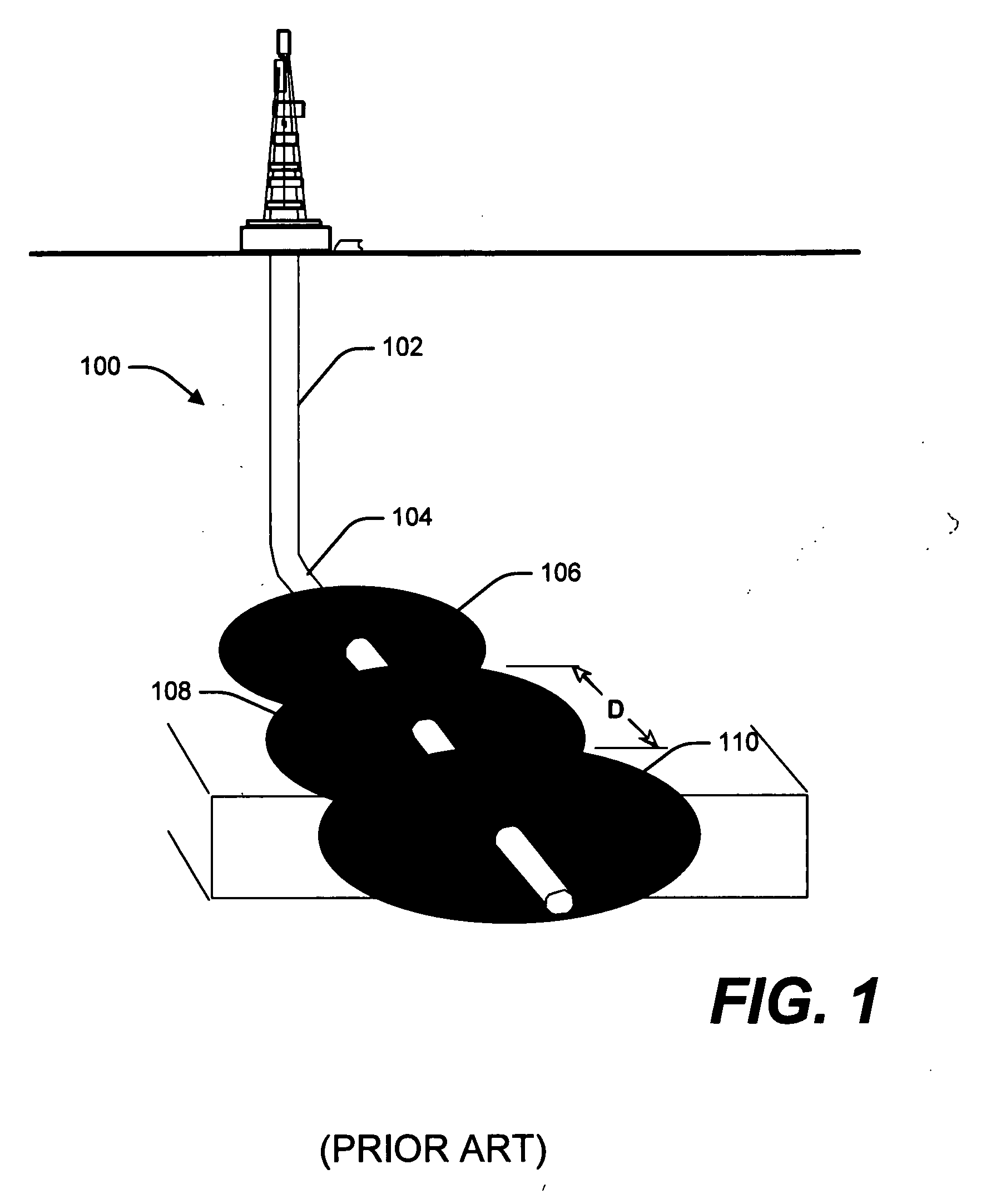
In the past, fracturing typically took place in well bores that were cased and perforated.
When many fractures are induced in a well bore, the geomechanical stress caused by fractures on each other can no longer be ignored.
Current fracturing modeling methods, however, do not account for geomechanical stresses caused by one fracture on another.

Method used


Image

  • Methods for geomechanical fracture modeling
  • Methods for geomechanical fracture modeling
  • Methods for geomechanical fracture modeling

Examples


Embodiment Construction

[0031]The present invention relates generally to methods for designing and optimizing the number, placement, and size of fractures in a subterranean formation and more particularly to methods that account for stress interference from other fractures when designing and optimizing the number, placement, and size of fractures in the subterranean formation. The present invention may be applied to vertical or horizontal wells. Furthermore, the present invention may be used on cased well bores or open holes.

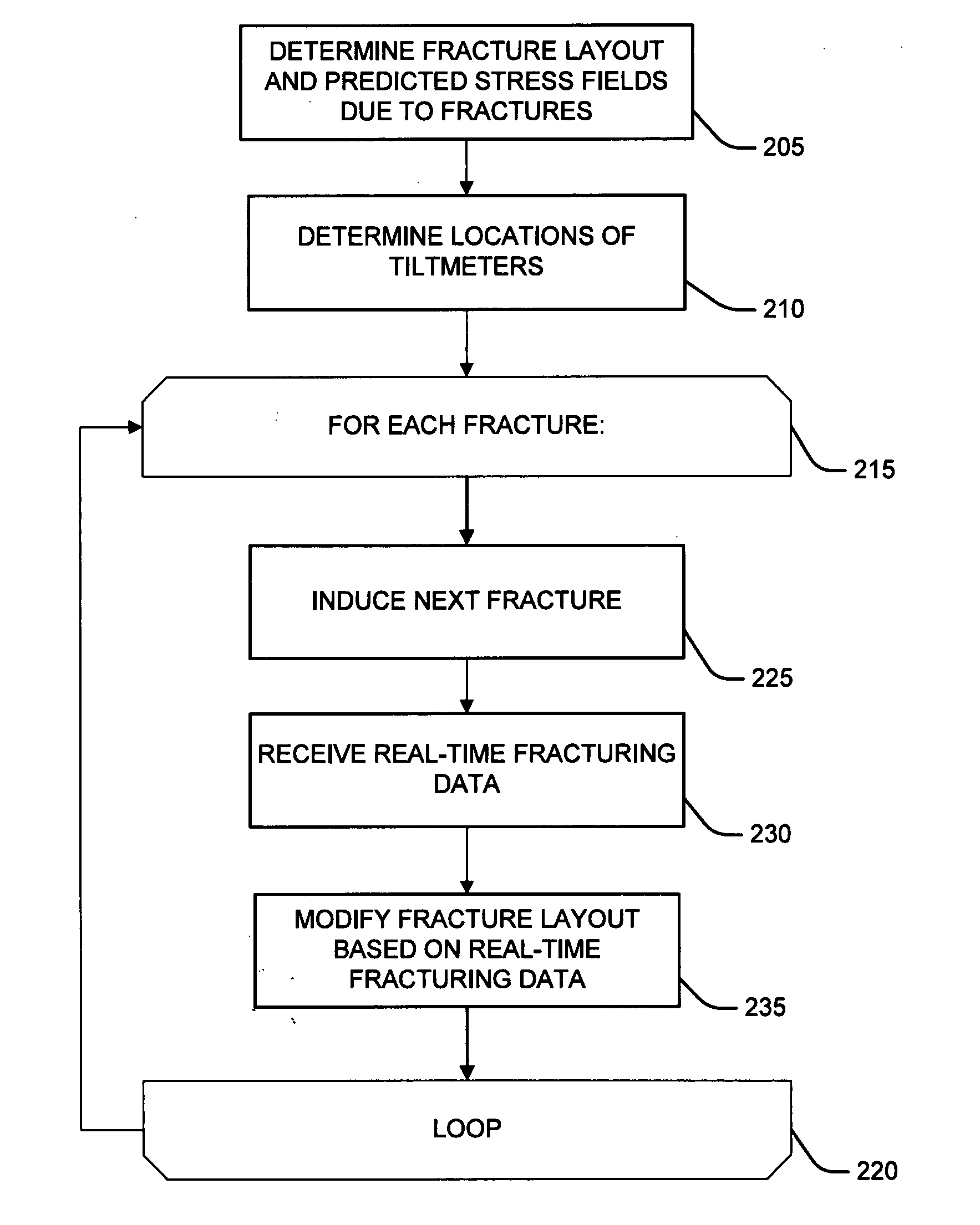
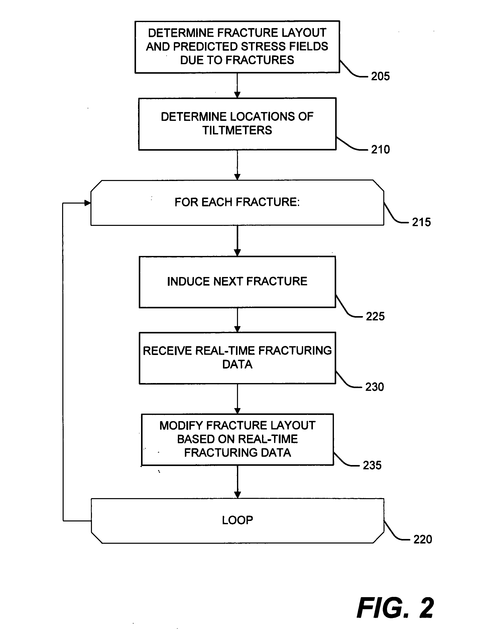
[0032]FIG. 2 depicts a flow chart of an exemplary embodiment of the methods according to the present invention. The method determines a fracture layout and one or more predicted stress fields due to the predicted fractures (block 205, which is shown in greater detail in FIG. 3). The method determines the locations of one or more tiltmeters to measure surface deformation caused by the predicted fractures (block 210). The method enters a loop and loops once for each fracture induced in t...


PUM


Abstract

The present invention relates generally to methods for designing and optimizing the number, placement, and size of fractures in a subterranean formation and more particularly to methods that account for stress interference from other fractures when designing and optimizing the number, placement, and size of fractures in the subterranean formation. The present invention optimizes the number, placement and size of fractures in a subterranean formation. The present invention determines one or more geomechanical stresses induced by each fracture based on the dimensions and location of each fracture, including surface deformations caused by each fracture. The present invention determines a maximum number of fractures and a predicted stress field based on the geomechanical stresses induced by each of the fractures.

Description

CROSS-REFERENCE TO RELATED APPLICATIONS[0001]This application is related to U.S. patent application Ser. No. 10 / 728,295, filed Dec. 4, 2003.BACKGROUND OF THE INVENTION[0002]The present invention relates generally to methods for designing and optimizing the number, placement, and size of fractures in a subterranean formation and more particularly to methods that account for stress interference from other fractures when designing and optimizing the number, placement, and size of fractures in the subterranean formation.[0003]One method typically used to increase the effective drainage area of well bores penetrating geologic formations is fracture stimulation. Fracture stimulation comprises the intentional fracturing of the subterranean formation by pumping a fracturing fluid into a well bore and against a selected surface of a subterranean formation intersected by the well bore. The fracturing fluid is pumped at a pressure sufficient that the earthen material in the subterranean format...

Claims


Application Information

Patent Timeline
Patent Type & Authority Applications(United States)
IPC IPC(8): G06F17/50
CPCE21B43/26G01V2210/646G01V99/005E21B49/00G01V20/00
Inventor SOLIMAN, MOHAMED Y.EAST, JR., LOYD E.FULTON, DWIGHT D.
Owner HALLIBURTON ENERGY SERVICES INC
Learn More