Disk cartridge

a technology of disk cartridges and cartridges, which is applied in the field of disk cartridges, can solve the problems of limited maximum allowable size of optical heads, scratched data storage sides, and difficult design of small cartridges with big openings

Inactive Publication Date: 2009-05-14
PANASONIC CORP
View PDF7 Cites 11 Cited by
  • Summary
  • Abstract
  • Description
  • Claims
  • Application Information

AI Technical Summary

Benefits of technology

[0008]In order to overcome at least one of these problems, the present invention has an object of provid

Problems solved by technology

That is to say, it is difficult to design a small cartridge with big openings.
As a result, in disk camcorders and other portable electronic devices that use a small cartridge, the maximum allowable size of the optical head is limited, which is a problem.
In addition, to allow such a positioning error, the disk needs to be movable in that space.
In that case, however, the disk could move inconstantly within the disk cartridge to possibly get its dat

Method used


Image

  • Disk cartridge
  • Disk cartridge
  • Disk cartridge

Examples


embodiment 1

[0062]Hereinafter, a first preferred embodiment of the present invention will be described.

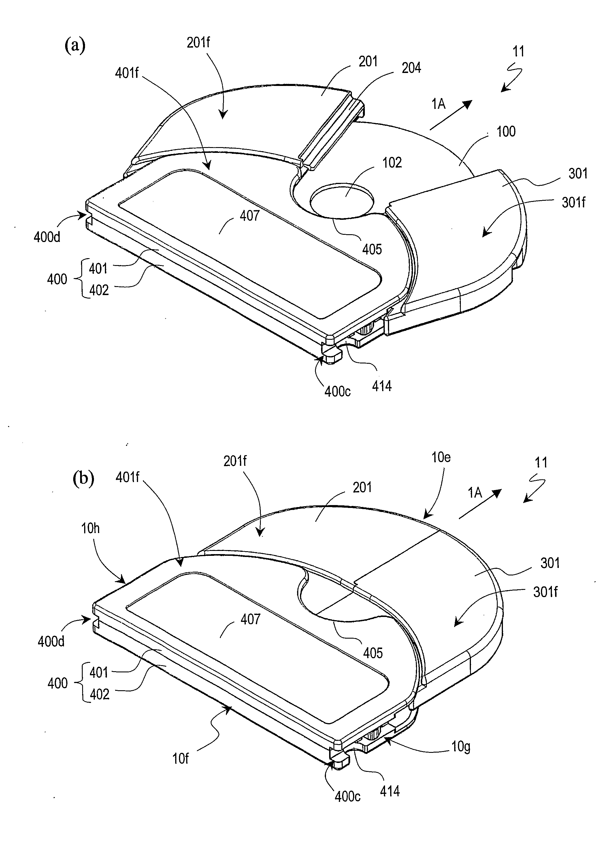
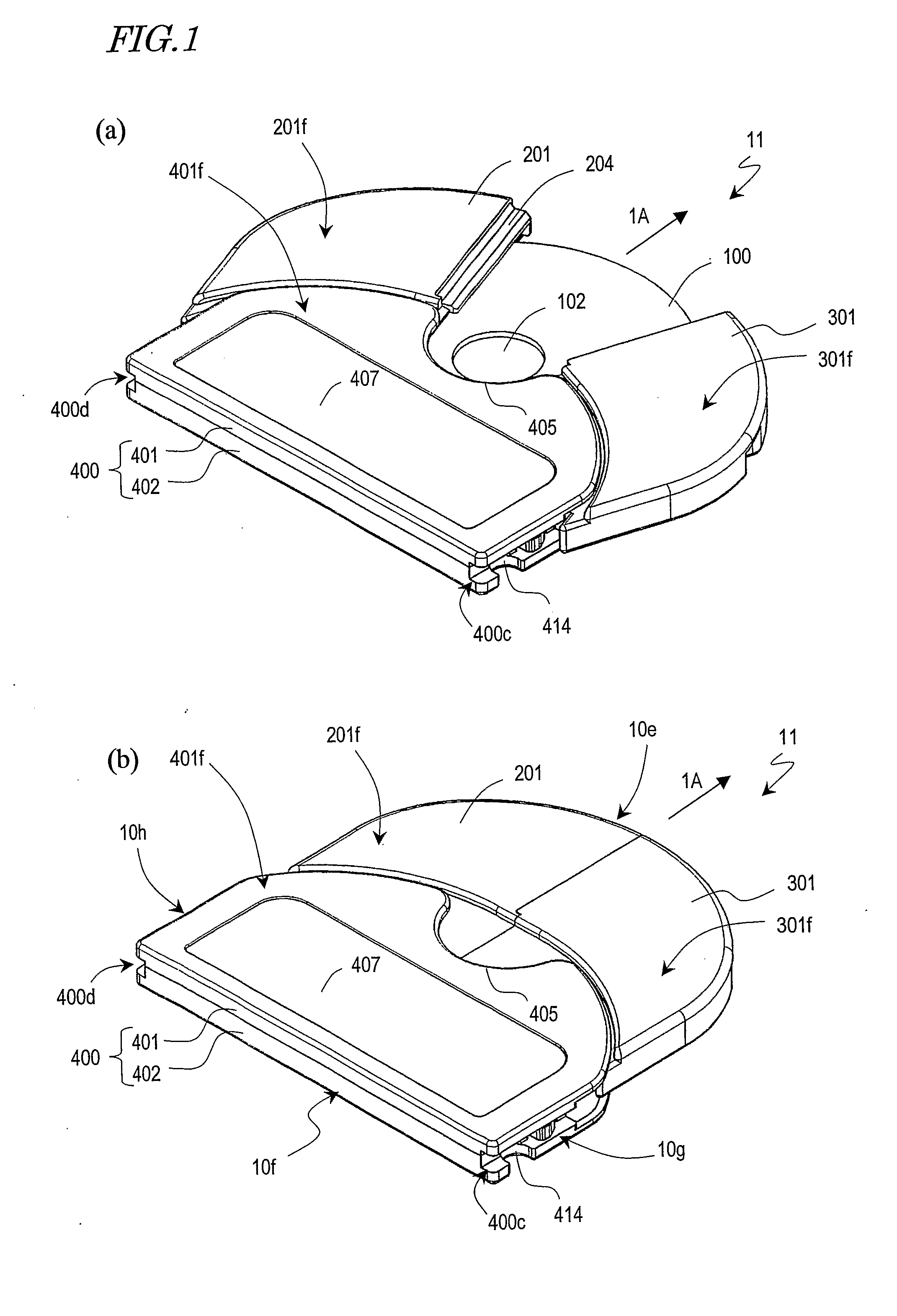
[0063]FIG. 1(a) is a perspective view of a disk cartridge 11, as viewed from above the cartridge, illustrating a situation where a disk 100 is enclosed in the cartridge and first and second disk storage portions 201 and 301 are opened. On the other hand, FIG. 1(b) is a perspective view of the disk cartridge 11, as viewed from above the cartridge, illustrating a situation where the first and second disk storage portions 201 and 301 are closed.

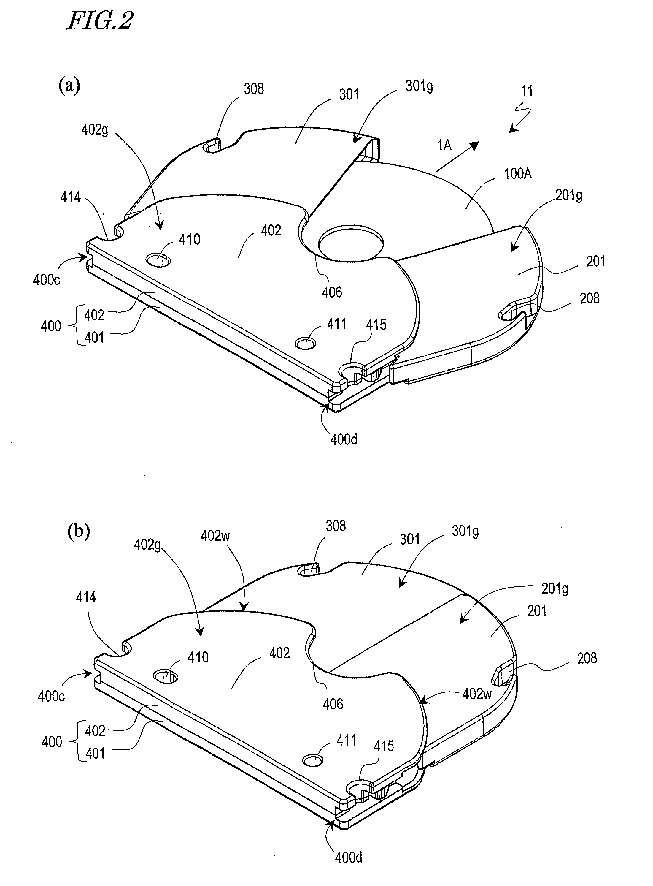
[0064]FIG. 2(a) is a perspective view of the disk cartridge 11, as viewed from under the data storage side 100A of the disk, illustrating a situation where the disk 100 is enclosed in the cartridge and the first and second disk storage portions 201 and 301 are opened. On the other hand, FIG. 2(b) is a perspective view of the disk cartridge 11, as viewed from under the data storage side 100A of the disk, illustrating a situation where the first and second d...

embodiment 2

[0133]Hereinafter, a second preferred embodiment of a disk cartridge according to the present invention will be described.

[0134]FIG. 12(a) is a perspective view of a disk cartridge 12, as viewed from above the cartridge, illustrating a situation where a disk 100 is enclosed in the cartridge and first and second disk storage portions 201 and 301 are opened. On the other hand, FIG. 12(b) is a perspective view of the disk cartridge 12, as viewed from above the cartridge, illustrating a situation where the first and second disk storage portions 201 and 301 are closed.

[0135]FIG. 13(a) is a perspective view of the disk cartridge 12, as viewed from under the data storage side 100A of the disk, illustrating a situation where the disk 100 is enclosed in the cartridge and the first and second disk storage portions 201 and 301 are opened. On the other hand, FIG. 13(b) is a perspective view of the disk cartridge 12, as viewed from under the data storage side 100A of the disk, illustrating a sit...

embodiment 3

[0158]Hereinafter, a third preferred embodiment of a disk cartridge according to the present invention will be described. FIGS. 20(a) and 21(a) are respectively a perspective view and a plan view illustrating how a disk cartridge 13 without the supporting base member upper shell 401 and the first and second locking members 501 and 601 looks when the first and second disk storage portions 201 and 301 are opened. FIGS. 20(b) and 21(b) are respectively a perspective view and a plan view illustrating how the disk cartridge 13 without the supporting base member upper shell 401 looks when the first and second disk storage portions 201 and 301 are opened.

[0159]In these drawings, any member of the disk cartridge 13, having the same function as the counterpart of the first preferred embodiment described above, is identified by the same reference numeral as that used for the first preferred embodiment.

[0160]The disk cartridge 13 can assume not only a first opened state in which the chucking h...


PUM


Abstract

A disk cartridge according to the present invention includes first and second disk storage portions, each of which has a space to partially store a disk with at least one data storage side. When closed up, the first and second disk storage portions enclose the disk entirely. The disk cartridge further includes a supporting base member with a disk storage portion rotation supporting portion that supports rotatably the first and second disk storage portions so as to make or cover an opening with respect to the disk. The opening is used to get the disk chucked externally and to allow a head to access the data storage side of the disk and read and/or write data from/on that side. At least a portion of the supporting base member overlaps with the first and second disk storage portions so as to prevent the first and second disk storage portions from moving perpendicularly to the disk.

Description

TECHNICAL FIELD[0001]The present invention relates to a disk cartridge to enclose a disklike data storage medium such as an optical disk or a magnetic disk.BACKGROUND ART[0002]Various disk cartridges to enclose a disklike data storage medium have been proposed so far.[0003]For example, Japanese Patent Application Laid-Open Publication No. 9-153264 discloses a disk cartridge in which a disklike storage medium with one or two data storage sides (which will be simply referred to herein as a “disk”) is fully enclosed in a disk storage portion that is provided inside of a supporting base member consisting of upper and lower housings. The supporting base member has a chucking hole for allowing the turntable of a spindle motor and a damper to chuck a given disk and a head access window for allowing a head to read and write data from / on the disk. The chucking hole and the head access window are continuous with each other, and therefore, dust easily enters the cartridge or a finger mark is o...

Claims


Application Information

Patent Timeline
IPC IPC(8): G11B23/03
CPCG11B23/0316G11B23/0308
Inventor TAKIZAWA, TERUYUKIINATA, MASAHIROEZAWA, KOZO
Owner PANASONIC CORP
Why Eureka
Try Eureka