Medical Instrument For Manipulation Of An Uterus

Active Publication Date: 2009-05-21
KARL STORZ GMBH & CO KG
View PDF13 Cites 38 Cited by
  • Summary
  • Abstract
  • Description
  • Claims
  • Application Information

AI Technical Summary

Benefits of technology

[0010]The sliding displacement of the bell-shaped element along the rod-shaped body can be done easily and quickly, and without rotating the two components relative to each other.
[0011]When the medical instrument designed in this way is to be inserted and positioned, the bell-shaped element can first be displaced in the proximal direction to the end of the rod-shaped body, such that the bell-shaped element does not block the operator's view during insertion of the distal end section of the rod-shaped body into the uterus. The operator can insert the distal end section of the rod-shaped body quickly and safely through the vagina into the uterus, and the position of the distal end section of the rod-shaped body can be better seen by the operator and can be cor

Problems solved by technology

A disadvantage of this medical instrument is that the axial position of the bell-shaped element on the rod is changed by a rotational movement between the bell-shaped element and the rod.
In order to move the bell-shaped element from a proximal end to a distal end, the operator has to turn either the rod of the bell-shaped element approximately 20 to 25 times. This is awkward, and quite a long time is taken to insert and position the medical instrument in the body of the patient.
A further disadvantage of said instrument is that the bell-shaped element is arranged on the distal end section of the

Method used


Image

  • Medical Instrument For Manipulation Of An Uterus
  • Medical Instrument For Manipulation Of An Uterus
  • Medical Instrument For Manipulation Of An Uterus

Examples


Embodiment Construction

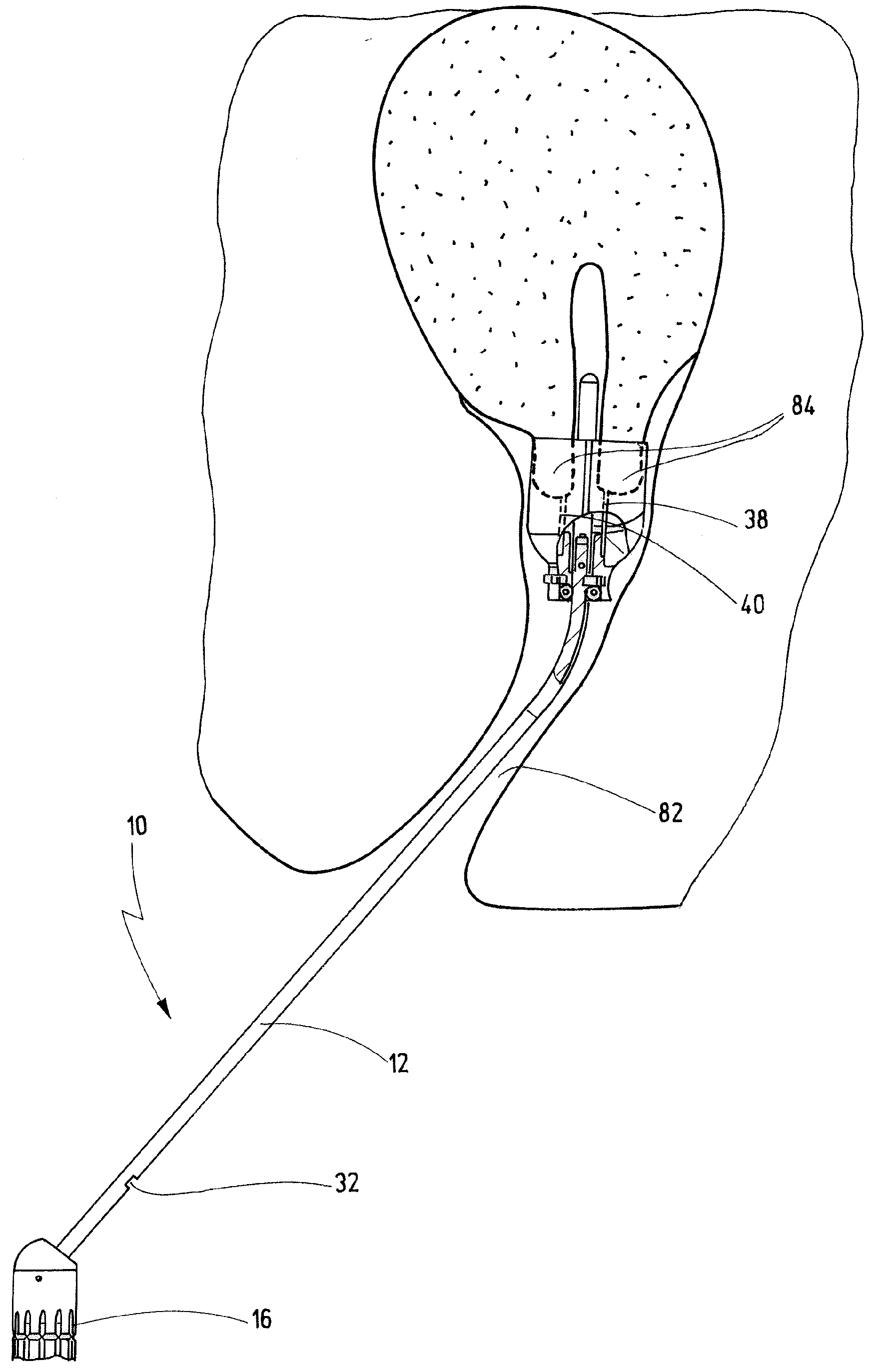
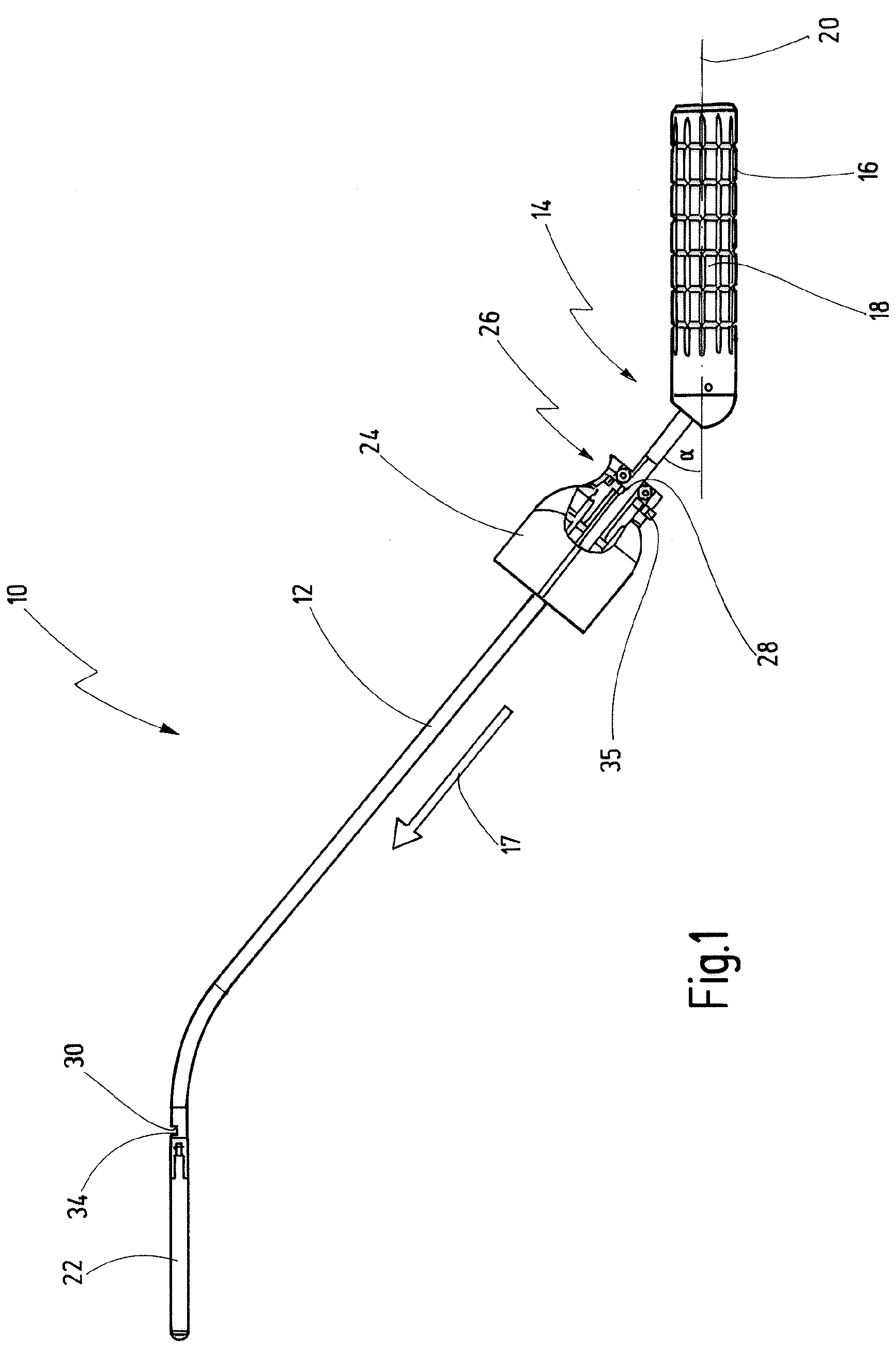
[0055]A medical instrument shown in FIG. 1, and used for manipulation of an uterus, is designated in its entirety by reference number 10.

[0056]The medical instrument 10 according to the invention has a rod-shaped body 12. A handle 16 is arranged at a proximal end 14 of the rod-shaped body 12. A notched pattern 18 is cut into an outer face of the handle 16, such that the medical instrument 10 can be gripped firmly and securely by a human hand in the area of the handle 16.

[0057]The rod-shaped body 12 is connected to the handle 16 in such a way that the rod-shaped body 12 forms an angle α of ca. 45° with respect to a longitudinal axis 20 of the handle 16.

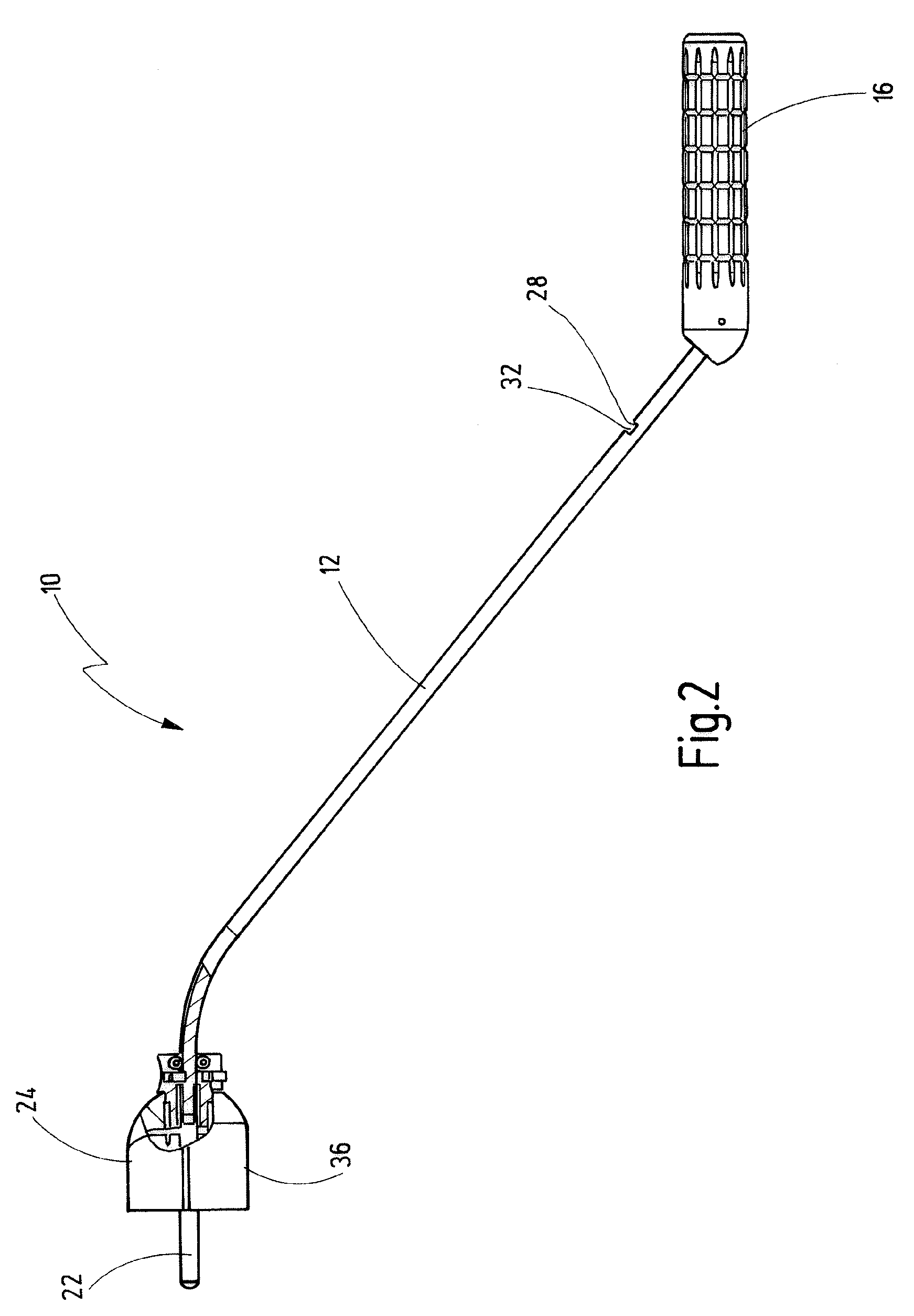
[0058]A distal rectilinear portion 22 of the rod-shaped body 12 is bent out from the longitudinal axis of the rod-shaped body 12, specifically in such a way that the distal end section 22 of the rod-shaped body 12 and the handle 16 are arranged parallel to each other.

[0059]A bell-shaped element 24 is arranged on the rod-shaped body 12,...


PUM


Abstract

A medical instrument has a rod-shaped body which has a distal end section which can be inserted through a vagina into an uterus. A bell-shaped element is mounted on the rod-shaped body. The bell-shaped element being slidingly displaceable along said rod-shaped body at least between an axial position on said rod-shaped body close to a proximal end thereof and up to said distal end section inserted in an uterus.

Description

BACKGROUND OF THE INVENTION[0001]The invention relates to a medical instrument for manipulation of an uterus, with a rod-shaped body whose distal end section can be inserted through the vagina into the uterus, said rod-shaped body carrying a bell-shaped element that can be moved to and fro along the rod-shaped body.[0002]A medical instrument that is used for manipulation of an uterus and that has these design features is known from US 2003 / 0187334 A1.[0003]Medical instruments of this kind, also called uterus manipulators, are used, among other reasons, to bring the uterus to a desired position for laparoscopic examinations of the lower abdominal region of female patients or in preparation for a surgical intervention. This is done, for example, in order to be able to examine a concealed surface of the uterus or to perform a surgical intervention, for example a hysterectomy (removal of the uterus).[0004]The medical instrument mentioned at the outset has a rectilinear rod, which is pro...

Claims


Application Information

Patent Timeline
IPC IPC(8): A61B17/42
CPCA61B17/4241
Inventor CHRISTIAN, WALTERDONNEZ, JACQUES
Owner KARL STORZ GMBH & CO KG
Why Eureka
Try Eureka