
Joint Construction, Connector Sleeve, A Coupling Assembly, and a Method for Preparation

a technology for connecting cables and connectors, which is applied in the direction of screw threaded joints, mechanical equipment, etc., can solve the problems of time-consuming and expensive maintenance of individual connector parts, and achieve the effect of reducing manufacturing costs, installation time, and/or inventory concerns associated with maintaining separate inventories of conduit sections and couplers

Inactive Publication Date: 2009-05-28
ALLIED TUBE CONDUIT
View PDF6 Cites 2 Cited by
  • Summary
  • Abstract
  • Description
  • Claims
  • Application Information

AI Technical Summary

Benefits of technology

The patent describes a joint construction for conduit that allows two sections of conduit to be securely connected together. The connection is made using a coupling member, a connector sleeve, a compression washer, and an internally threaded annular gland nut. The joint is designed to resist twisting and separation of the conduit sections, and it is easy to assemble and disassemble. The use of an integrated coupling assembly reduces manufacturing costs and installation time, and it also allows for the efficient use of inventory. Overall, the joint construction provides a reliable and efficient connection between conduit sections.

Problems solved by technology

Maintaining inventory of and installing the individual connector parts takes time and costs money.

Method used


Image

  • Joint Construction, Connector Sleeve, A Coupling Assembly, and a Method for Preparation
  • Joint Construction, Connector Sleeve, A Coupling Assembly, and a Method for Preparation
  • Joint Construction, Connector Sleeve, A Coupling Assembly, and a Method for Preparation

Examples


Embodiment Construction

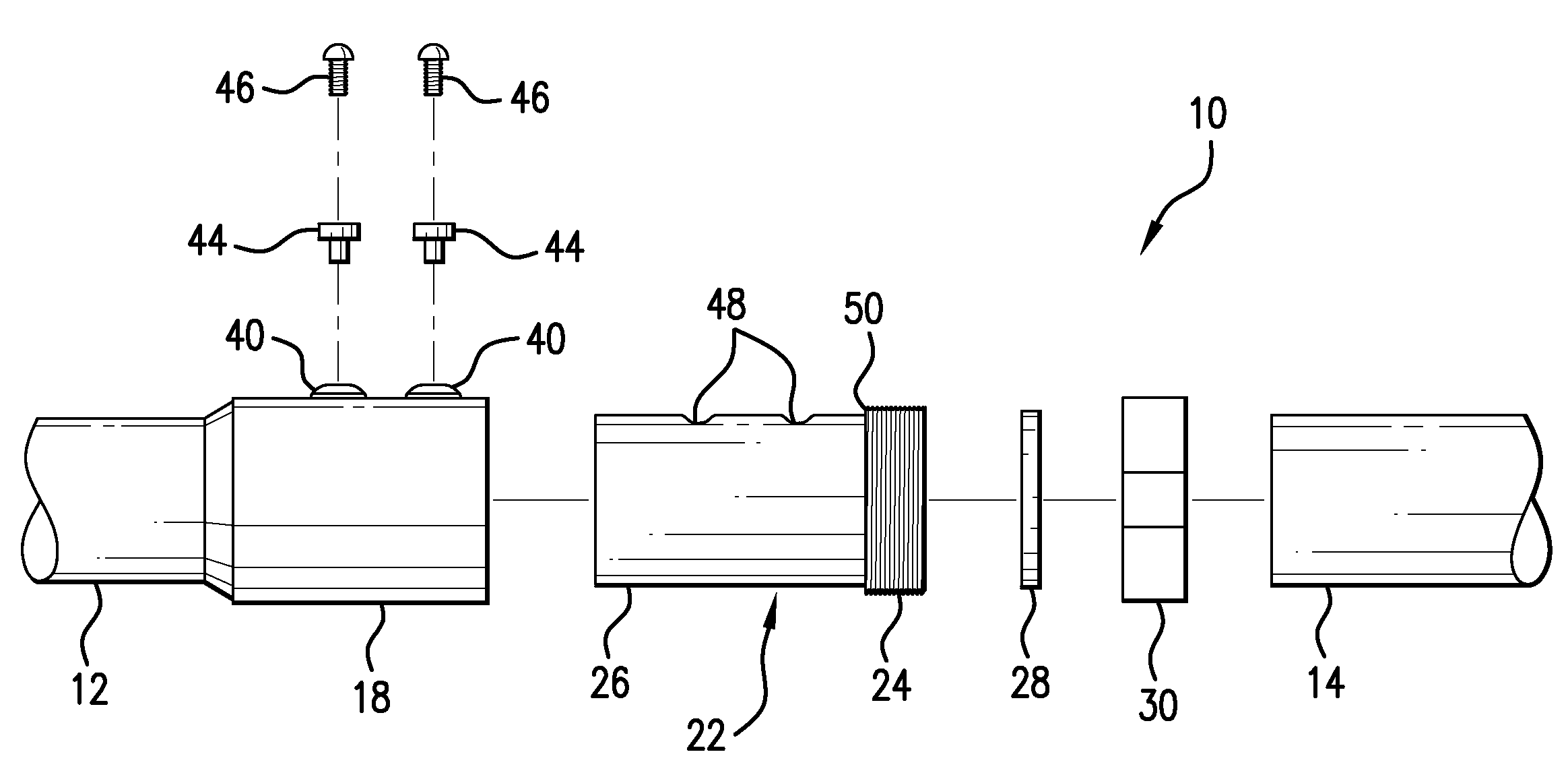
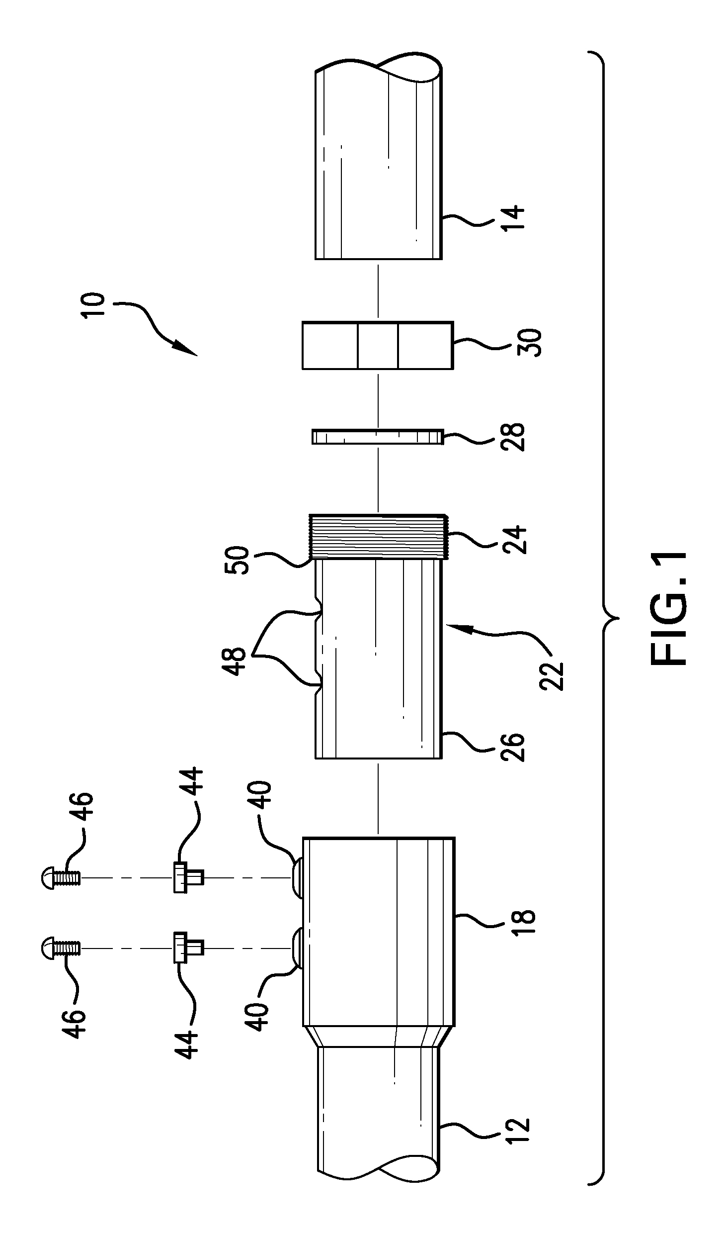
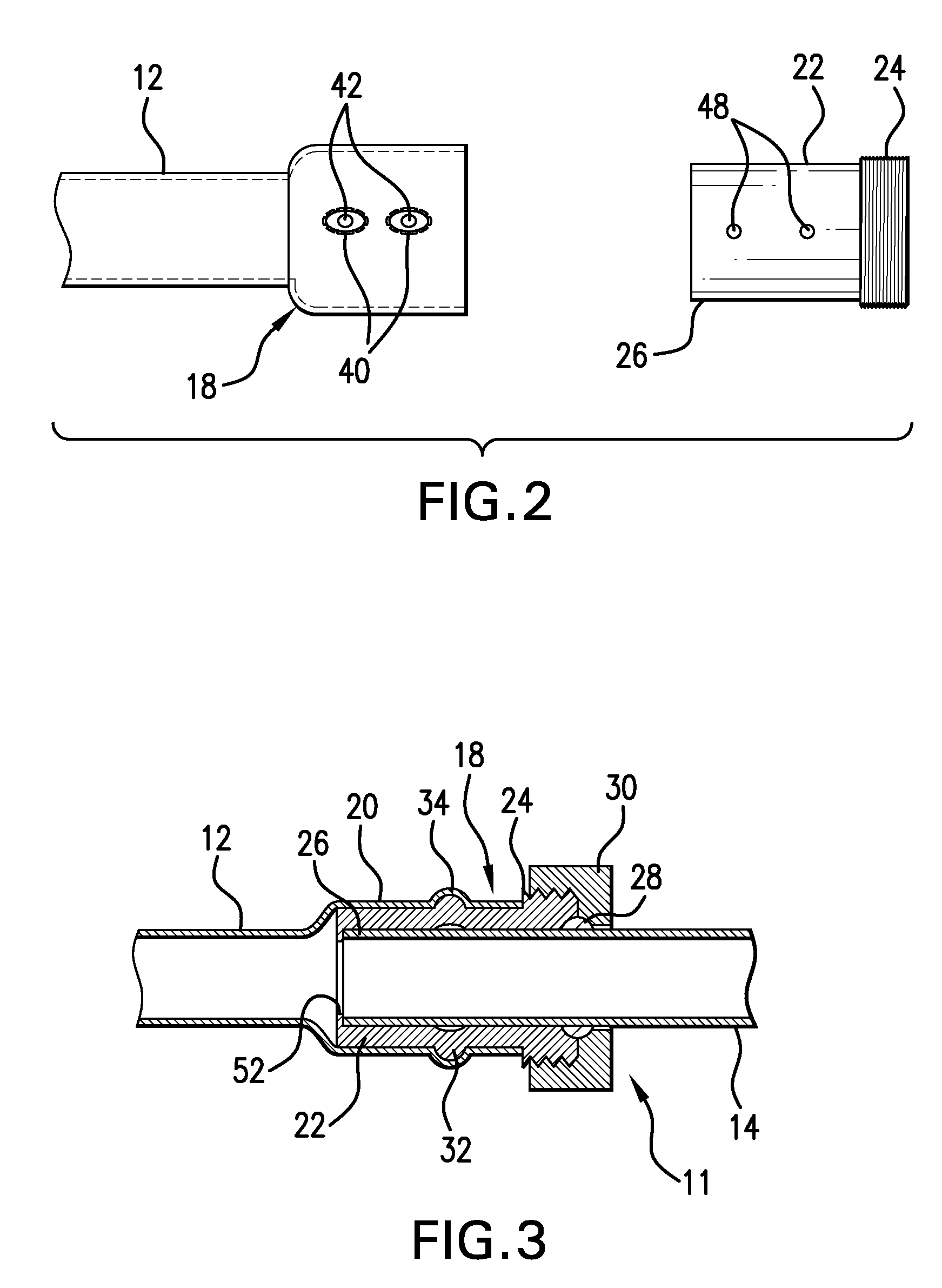
[0018]With reference to the drawing figures, there appears a conduit joint construction 10 (FIG. 1) according to a first embodiment and a conduit joint construction 11 (FIG. 3) for connecting two conduit sections 12, 14 in coaxial, end-to-end fashion. The conduit 12 has at least one receiving end 18. The receiving end 18 is defined by a swaged or bell portion 20. The bell portion 20 has an enlarged diameter with respect to the conduit 34 is designed to receive a connector sleeve 22. The conduit is preferably electrical metallic tubing and may be formed of steel, aluminum or aluminum alloy, or other metal or metal alloy. Other conduit materials are also contemplated, such as PCV and other plastics.

[0019]The connector sleeve 22 has an externally threaded end 24 and an insertion end 26. Furthermore, the connector sleeve 22 defines an axial channel or bore having an internal diameter sized to receive an end of the second conduit 14. The insertion end 26 of the connector sleeve 22 can be...


PUM

PropertyMeasurementUnit
lengthsaaaaaaaaaa
diameteraaaaaaaaaa
resistanceaaaaaaaaaa

Abstract

A connector sleeve for joining conduit, and a joint construction, and a coupling assembly for joining conduit; and a method for joining conduit using a coupling assembly.

Description

FIELD OF THE INVENTION[0001]The present disclosure relates to a joint construction for conduit, a coupling assembly for joining conduit, a connector sleeve for joining conduit, and to a method for joining conduit using a coupling assembly. It finds particular application in conjunction with electrical metallic tubing and will be described herein primarily by way of reference thereto; however, it will be appreciated that the invention finds utility in conjunction with all manner of conduits, including pipes, tubes, ducts, and the like.BACKGROUND OF THE INVENTION[0002]Electrical metallic tubing (EMT) is thin-wailed tubing used to contain is and protect electrical wires. EMT is commonly used in warehouses, gymnasiums, factories, and the like. Such conduit is traditionally manufactured in ten (10) foot lengths. The conduit sections can be connected end-to-end for use in applications requiring longer sections. Conduit connectors and conduit coupling assemblies are well known in the art. ...

Claims


Application Information

Patent Timeline
Patent Type & Authority Applications(United States)
IPC IPC(8): B23P17/00
CPCF16L19/00F16L19/04Y10T29/49428F16L15/08Y10T29/4943F16L19/075
Inventor SCARTOZZI, GIULIO
Owner ALLIED TUBE CONDUIT
Learn More