

Vehicle locking device and vehicle locking method
- Summary
- Abstract
- Description
- Claims
- Application Information
AI Technical Summary
Benefits of technology
Problems solved by technology
Method used
Image

Examples
Embodiment Construction
[0024]Preferred embodiments of the vehicle locking device will be explained with reference to accompanying drawings.
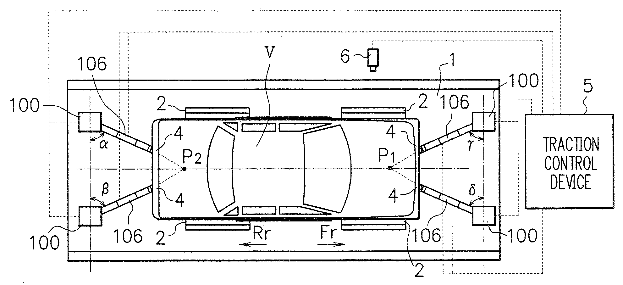
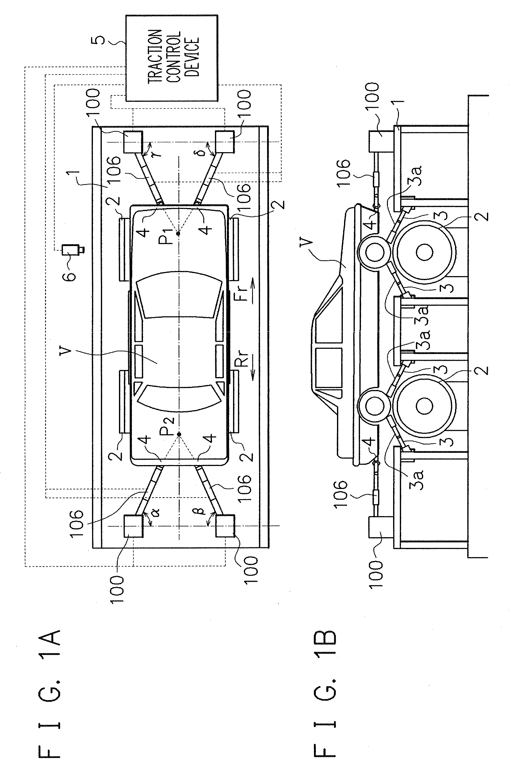
[0025]FIGS. 1A and 1B illustrate a schematic configuration of a chassis dynamometer equipped with a vehicle locking device of the embodiment, wherein FIG. 1A is a schematic plan view, and FIG. 1B is a schematic side elevation.
[0026]The chassis dynamometer assumes a four-wheel-drive vehicle as a test vehicle V to be tested, has a pit floor 1 laid over a pit where the chassis dynamometer is placed thereon, and the test vehicle V is disposed and locked at a predetermined position on the pit floor 1. In FIG. 1A, the forward and rear directions of the test vehicle V are indicated by arrows Fr and Rr, respectively.
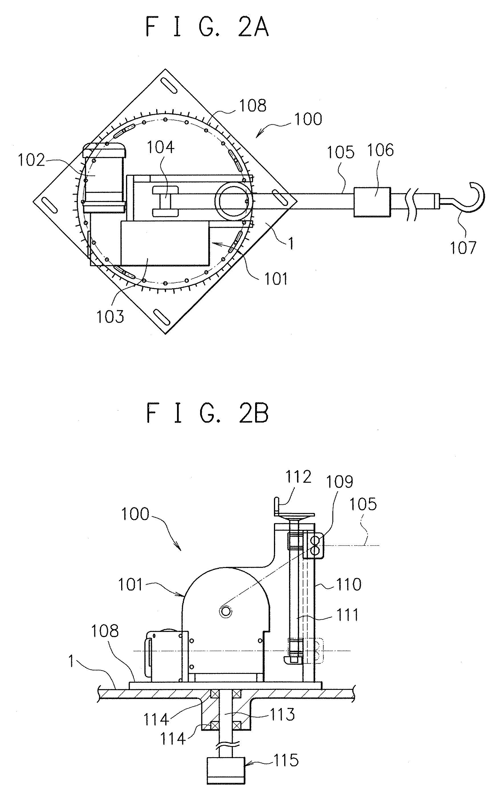
[0027]When the test vehicle V is disposed and locked at the predetermined position on the pit floor 1, first, four wheels of the test vehicle V are placed respectively on the correspondent rollers 2. The individual wheels are then positioned at the predetermined po...
PUM
 Abstract
Description
Claims
Application Information