Vortex air-oil separator system

a technology of air-oil separator and separator, which is applied in the direction of liquid degasification, separation process, machines/engines, etc., can solve the problems of loss of oil contained in air/oil mixture, unrecoverable oil, and high oil consumption

Active Publication Date: 2009-05-28
GENERAL ELECTRIC CO
View PDF14 Cites 51 Cited by
  • Summary
  • Abstract
  • Description
  • Claims
  • Application Information

AI Technical Summary

Problems solved by technology

Oil consumption arises from the method used to seal the engine sumps.
This flow ultimately contains oil that is unrecoverable unless adequately separated and delivered back to the sumps.
Oil that is contained in the air/oil mixture is lost when it is unable to centrifuge back into the sump through the vent hole due to rapidly escaping vent air.
However, air-oil separation is very poor in these conventional designs in cases where the axial distances are short between the radial entr

Method used


Image

  • Vortex air-oil separator system
  • Vortex air-oil separator system
  • Vortex air-oil separator system

Examples


Embodiment Construction

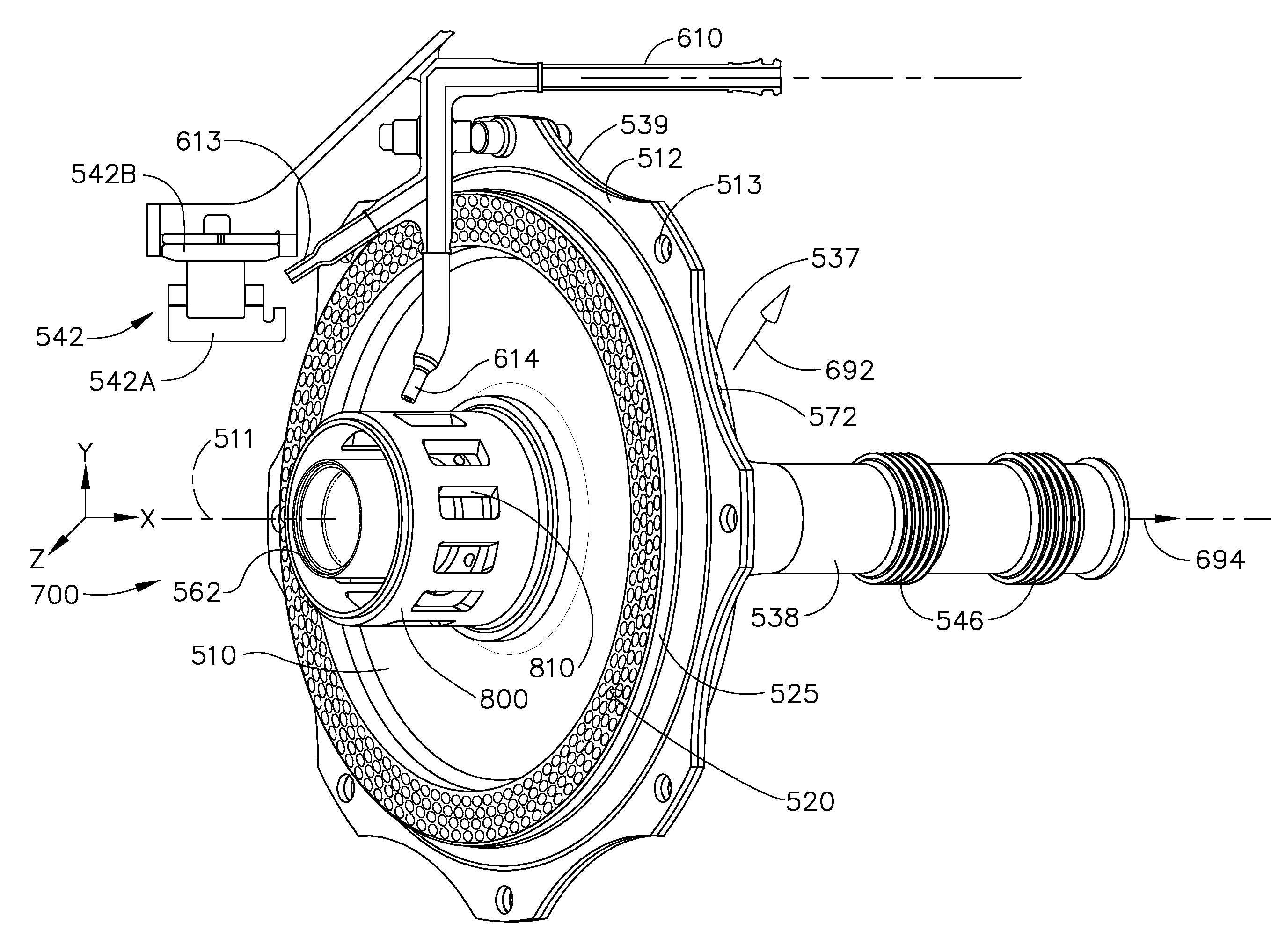
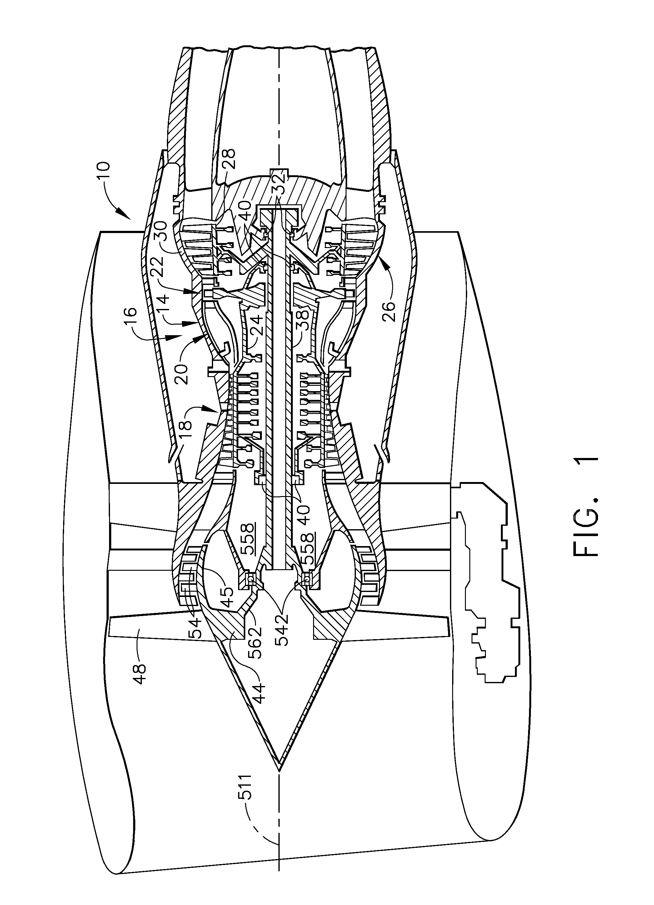
[0015]Referring to the drawings wherein identical reference numerals denote the same elements throughout the various views, FIG. 1 illustrates a gas turbine engine, generally designated 10, incorporating an exemplary embodiment of a vortex air-oil separator system of the present invention. The engine 10 has a longitudinal centerline or axis 511 and an outer stationary annular casing 14 disposed concentrically about and coaxially along the axis 511. The engine 10 includes a gas generator core 16 which is composed of a multi-stage compressor 18, a combustor 20, and a high pressure turbine 22, either single or multiple stage, all arranged coaxially about the longitudinal axis or center line 511 of the engine 10 in a serial, axial flow relationship. An annular outer drive shaft 24 fixedly interconnects the compressor 18 and high pressure turbine 22.

[0016]The core 16 is effective for generating combustion gases. Pressurized air from the compressor 18 is mixed with fuel in the combustor 2...


PUM

PropertyMeasurementUnit
Angleaaaaaaaaaa
Velocityaaaaaaaaaa

Abstract

The present invention provides a vortex generator that may be used in systems for separating oil from air oil mixtures. The vortex generator comprises a rotating disk having a rim having a plurality of passages extending through it and a cavity formed by the rotating disk and a cavity wall wherein a vortex is created when there is a flow through the plurality of passages into the cavity.

Description

CROSS REFERENCE TO RELATED APPLICATIONS[0001]This specification is related to and incorporates herein by reference U.S. application Ser. No. ______, entitled “AIR-OIL SEPARATOR”, and U.S. application Ser. No. ______, entitled “FREE VORTEX AIR-OIL SEPARATOR”, which were filed concurrently with this application.BACKGROUND OF THE INVENTION[0002]This invention relates generally to gas turbine engines and more particularly to a vortex air oil separator system for recovering oil used to lubricate and cool bearings and other components of a gas turbine engine.[0003]Gas turbine engines typically include a core having a compressor for compressing air entering the core, a combustor where fuel is mixed with the compressed air and then burned to create a high energy gas stream, and a high pressure turbine which extracts energy from the gas stream to drive the compressor. In aircraft turbofan engines, a low pressure turbine located downstream from the core extracts more energy from the gas strea...

Claims


Application Information

Patent Timeline
IPC IPC(8): B01D19/00B01F7/10F16N7/34B01F27/73
CPCB01D45/14F01D25/18F16C2360/23F16C33/6685Y10S55/19F01M2013/0422
Inventor FANG, NINGANSTEAD, DUANE HOWARDPROCTOR, ROBERTSANGLI, PRADEEP HEMANTKANE, PRASAD LAXMANMOSCARINO, GARY PAULCORATTIYIL, BALAKINNAIRD, RAY HARRISPUGH, DAVID WILLIAMZENTGRAF, MARK EDEN
Owner GENERAL ELECTRIC CO
Why Eureka
Try Eureka