
Spread illuminating apparatus

Active Publication Date: 2009-05-28
MINEBEAMITSUMI INC
View PDF1 Cites 98 Cited by
  • Summary
  • Abstract
  • Description
  • Claims
  • Application Information

AI Technical Summary

Benefits of technology

[0024]According to the present invention, a spread illuminating apparatus of side light type is provided in which bright lines are suppressed from being generated in the neighborhood of a point light source such as an LED, and good brightness uniformity is achieved.

Problems solved by technology

However, a spread illuminating apparatus, in which a light introducing prism mechanism is formed at a light entrance surface of a light guide plate, a light emitting pattern is formed at a light reflecting surface of the light guide plate, a light diffusing pattern is formed at a light emitting surface of the light guide plate, and a light diffusing sheet and two prism sheets are disposed at the light emitting surface, has the following problem. FIG. 10 shows such a conventional spread illuminating apparatus as described above, in which while illumination light is emitted from the light emitting surface of the light guide plate in a uniform manner on the whole, two bright lines are visibly present symmetrically to each other in the neighborhood of a light entrance surface 101a of a light guide plate 101, close to which an LED 102 is disposed.
However, in order to achieve a small spread illuminating apparatus with a narrowed frame in which an area covered by a light blocking sheet thus becoming unusable as an illumination region (ineffective area) is reduced for the purpose of meeting ever increasing demands for further downsizing the apparatus, the generation of bright lines which deteriorate the brightness uniformity must be suppressed.

Method used


Image

  • Spread illuminating apparatus
  • Spread illuminating apparatus
  • Spread illuminating apparatus

Examples


Embodiment Construction

[0035]An exemplary embodiment of the present invention will be described with reference to the accompanying drawings. In the drawings, the configurations or the like of constituent components are exaggerated as appropriate for a better understanding of the present invention.

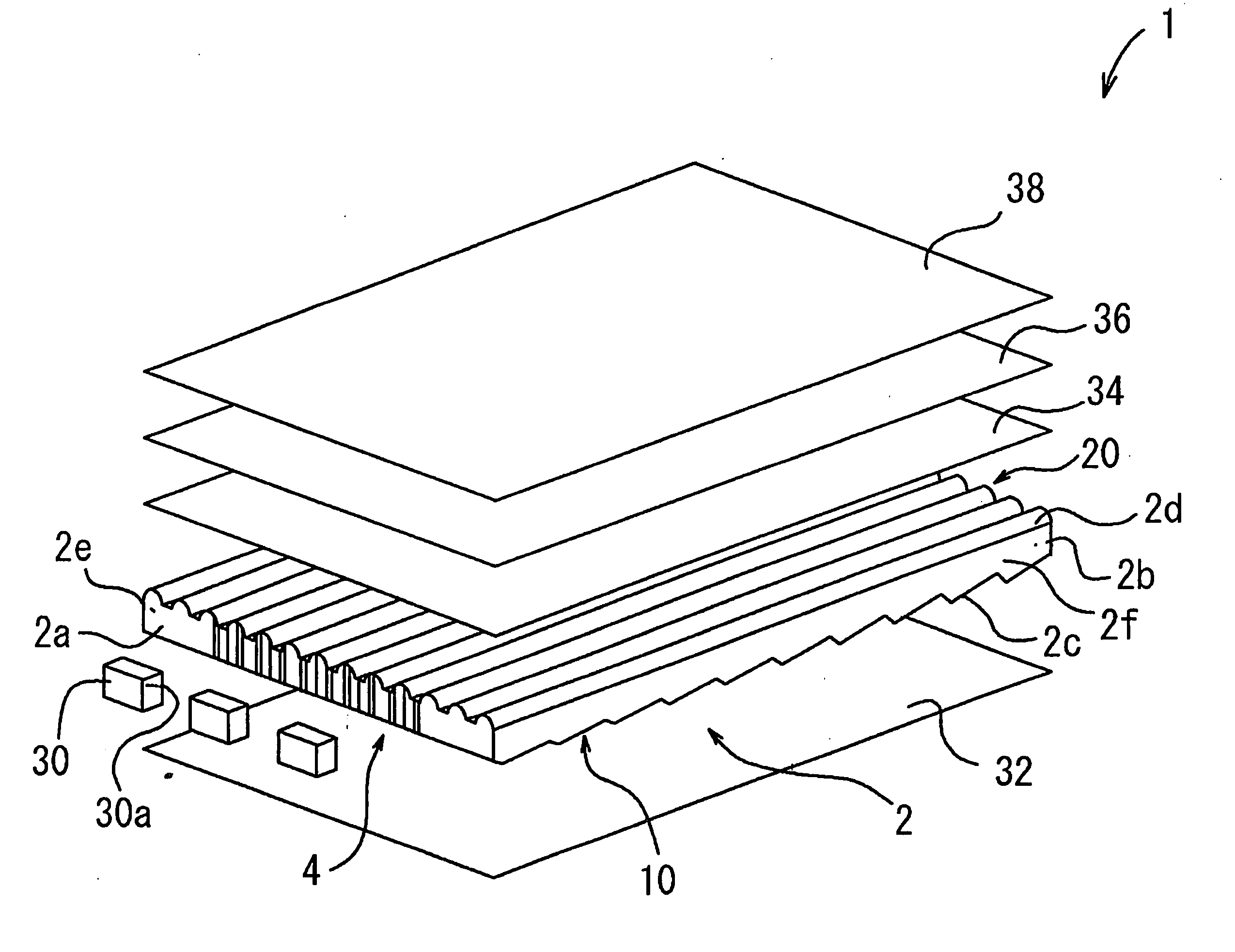
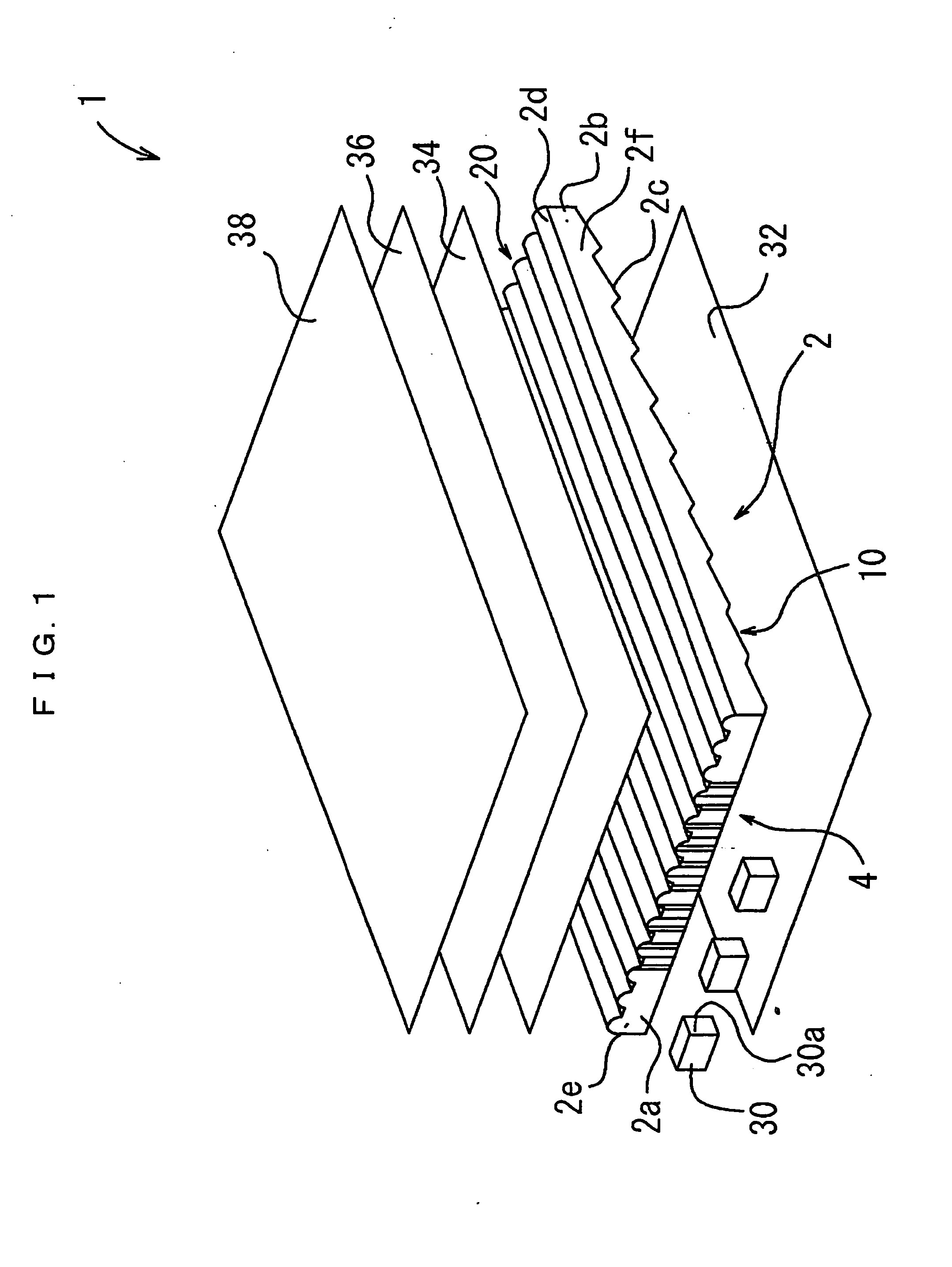
[0036]Referring to FIG. 1, a spread illuminating apparatus 1 according to an embodiment of the present invention includes a light guide plate 2 having a substantially rectangular shape, and LEDs 30 as point light sources disposed to face one side surface (light entrance surface) 2a of the light guide plate 2.

[0037]A light reflecting sheet 32 is disposed at one major surface, specifically a bottom surface (light reflecting surface) 2c of the light guide plate 2. The light reflecting sheet 32 is adapted to reintroduce into the light guide plate 2 light emitted from the LED 30 into the light guide plate 2 and leaking out from the bottom surface 2c. A light diffusing sheet 34 and a pair of prism sheets 36 and 38 are ...


PUM


Abstract

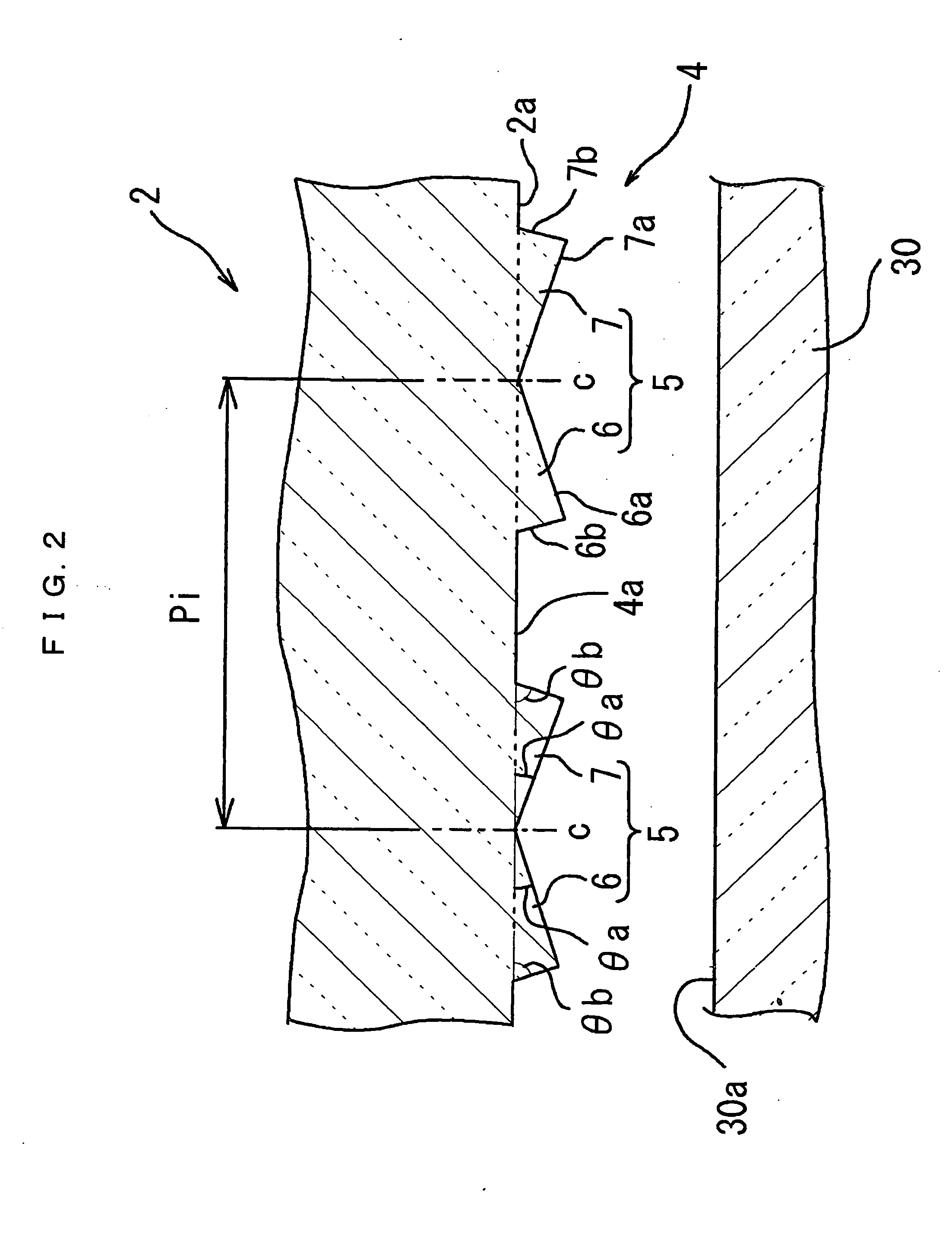
A spread illuminating apparatus is provided where: a light introducing prism mechanism is formed at a light entrance surface of a light guide plate wherein the prism mechanism includes a plurality of prism pieces extending in the thickness direction of the light guide plate and including first and second light incidence faces which have respective different inclination angles relative to the light entrance surface such that the first and second light incidence face are inclined relative to the light incidence surface at an angle ranging from 0 degree to 30 degrees and at an angle ranging from 45 degrees to 90 degrees; a light emitting pattern is formed at the bottom surface of the light guide plate such that prisms are continuously disposed in a step-like manner in the direction perpendicular to the light entrance surface; and a light diffusing pattern is formed at the top surface of the light guide plate such that arc prisms are disposed in the direction parallel to the light entrance surface.

Description

BACKGROUND OF THE INVENTION[0001]1. Field of the Invention[0002]The present invention relates to a spread illuminating apparatus of side light type, in which a point light source such as a light emitting diode (LED) is used as a light source, and more particularly to a spread illuminating apparatus suitable as a backlight for a liquid crystal display panel.[0003]2. Description of the Related Art[0004]A liquid crystal display (LCD) panel characterized in having a small thickness does not emit light by itself and therefore needs an illuminating means for displaying images. A spread illuminating apparatus of side light type, which is structured such that a light source is disposed at a side surface (light entrance surface) of a light guide plate disposed under an LCD panel, is widely used as such an illuminating means, especially in the filed of small portable information devices, such as a mobile phone.[0005]In order to achieve a high quality display on an LCD panel, it is always requ...

Claims


Application Information

Patent Timeline
IPC IPC(8): F21V8/00
CPCG02B6/0016G02B6/0068G02B6/0038G02B6/0021
Inventor KUNIMOCHI, TORU
Owner MINEBEAMITSUMI INC
Learn More