Direct backlight device

A backlight device, a direct-type technology, applied to lighting devices, fixed lighting devices, lighting device components, etc., can solve problems such as insufficient luminance uniformity, achieve suppression of luminance unevenness, and efficient use of high light beams High efficiency and brightness uniformity

Inactive Publication Date: 2010-06-23
ZEON CORP
View PDF18 Cites 2 Cited by
  • Summary
  • Abstract
  • Description
  • Claims
  • Application Information

AI Technical Summary

Problems solved by technology

However, only by forming a prism-like pattern on the surface of the light diffusion plate, the improvement of luminance uniformity is not sufficient

Method used


Image

  • Direct backlight device
  • Direct backlight device
  • Direct backlight device

Examples


Embodiment 1

[0111] Resin having an alicyclic structure as a transparent resin [Nippon Zeon Co., Ltd. (ZEON Corporation of Japan), Zeonora 1060R (ZEONER 1060R), water absorption 0.01%] 99.7 parts, and polysiloxane as a light diffusing agent Microparticles [GE Toshiba Silicon Co., Ltd. (GE Toshiba Silicon Company), Tospearl 120 (Tospearl 120)] composed of cross-linked polymers were mixed in 0.3 parts, kneaded with a two-screw extruder, and formed as a tow Shape extruded, and cut with a pelletizing machine (pelletizing machine), thereby manufacturing pellets (pellets) for light diffusion plates. From these pellets for a light diffusion plate, a test plate having a thickness of 2 mm and a thickness of 100 mm×50 mm with both sides smooth was molded using an extrusion molding machine [die bonding force: 1000 kN]. The total light transmittance and haze of this test plate were measured using the integrating sphere method color difference nephelometer in accordance with JIS K7361-1 and JIS K7136. ...

Embodiment 2

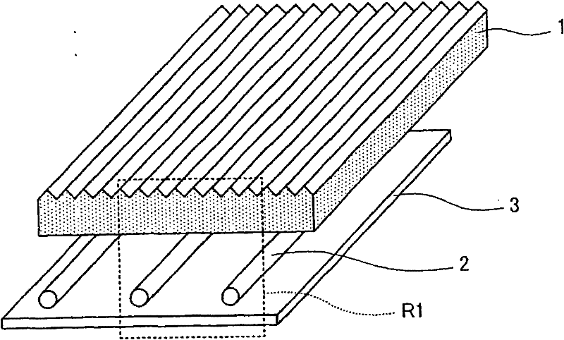
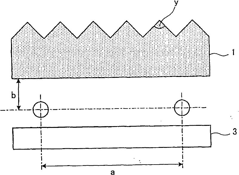
[0122] A reflective sheet (manufactured by Tsujiden Co., Ltd., RF188 (RF188 manufactured by TSUJIDEN)) was pasted on the inner surface of a milky white plastic case with an inner length of 300 mm, an inner width of 240 mm, and a depth of 11 mm. As a reflector, the distance from the bottom of the reflector was 4 mm. The distance a between the centers of the cold-cathode tubes was 25 mm, and eight cold-cathode tubes with a diameter of 4 mm and a length of 360 mm were arranged. ). For the backlight designed in this way, since the distance b between the center of the cold-cathode tube and the side of the cold-cathode tube of the light diffusion plate is 7 mm, the values ​​of a and b are substituted into (Formula 1), and the preferred range of the prism apex angle y is found to be 37.4

[0123] Here, the metal part of the mold is cut to prepare a mold that forms prism strips in a cross-sectional shape of connected isosceles triangles with an apex angle of 95° parallel to...

Embodiment 3

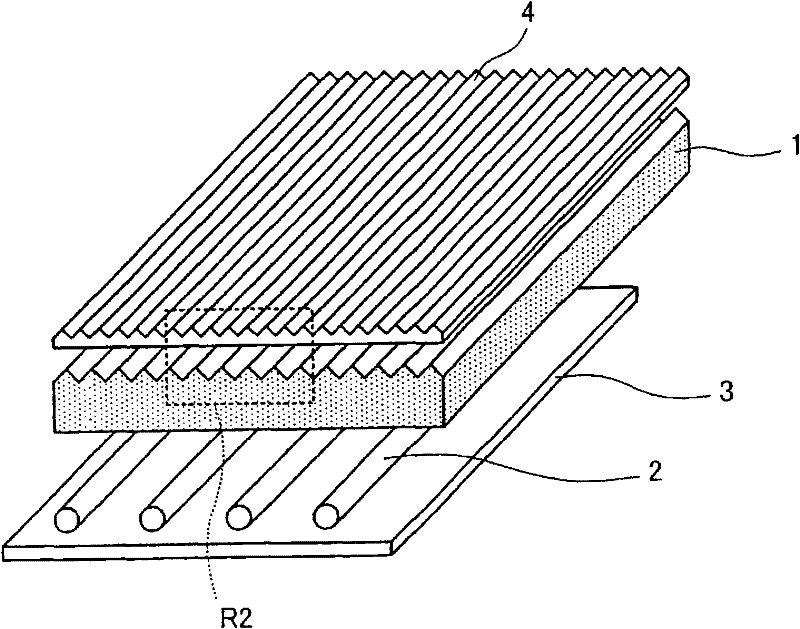
[0126] In this embodiment, a prism sheet is used in place of a reflective polarizer utilizing birefringence in such a manner that the long direction of the prism row is 90° from the cold cathode tube and is located on the side far from the light diffusion plate. Setting was carried out in the same manner as in Example 1, and a front-type backlight device 3 was fabricated and evaluated. Its average luminance is 3639cd / m 2 , the luminance uniformity is 0.4. The results are shown in Table 1. In addition, the luminance uniformity from the oblique direction was 0.6.


PUM


Abstract

A thin direct-under backlight capable of realizing a high uniformity ratio of luminance by suppressing periodic unevenness of luminance on the emission surface while maintaining a high utilization ratio of light beam through contrivance in design of the direct-under backlight. In the direct-under backlight comprising a plurality of liner light sources arranged parallel, a reflector and a light diffuser, a prism array of saw-tooth cross-section is provided on at least one major surface of the light diffuser. If the vertex angle of the prism array on the light diffuser is y (degree), the distance between the centers of adjacent linear light sources is a (mm), and the distance between the center of the linear light source and the surface of the light diffuser on the light source side is b (mm), the following relation is satisfied: 80 (b/a)+15<y<180 (b/a)+70.

Description

[0001] This application is a divisional application of the patent application for invention filed on August 23, 2005 by Zeon Corporation, Japan, with the name "Direct Backlight Device" and application number 200580028140.9. technical field [0002] The invention relates to a direct type backlight device. More specifically, the present invention relates to a direct type backlight device with high luminance and good luminance uniformity. Background technique [0003] Conventionally, as a backlight device for a liquid crystal display, a device using a cold-cathode tube as a light source has been widely used, and there are a type called an edge light type and a type called a direct type. The edge-light type backlight device is configured by arranging thin-tube cold-cathode tubes on the edge of the light guide plate, and the light incident from the end surface is repeatedly reflected in the light guide plate to output light on the main surface of the light guide plate. [0004] ...

Claims


Application Information

Patent Timeline
Patent Type & Authority Applications(China)
IPC IPC(8): F21S8/00F21V5/02F21V5/08
CPCG02F1/133604G02F1/133606F21V5/02G02F1/133605G02F2001/133607G02F1/133607
Inventor 草野贤次林昌彦塚田启介高桥靖典
Owner ZEON CORP
Why Eureka
Try Eureka