
Presence system and information processing equipment, dynamic buddy list generation method in presence system, and presence notification destination controlling method and its program for use with presence system

a technology for information processing equipment and presence information, applied in the field of presence information processing equipment, can solve the problems of unreasonably onerous task, unreliability of presence information, and disclosing presence information

Active Publication Date: 2009-05-28
NEC CORP
View PDF2 Cites 26 Cited by
  • Summary
  • Abstract
  • Description
  • Claims
  • Application Information

AI Technical Summary

Benefits of technology

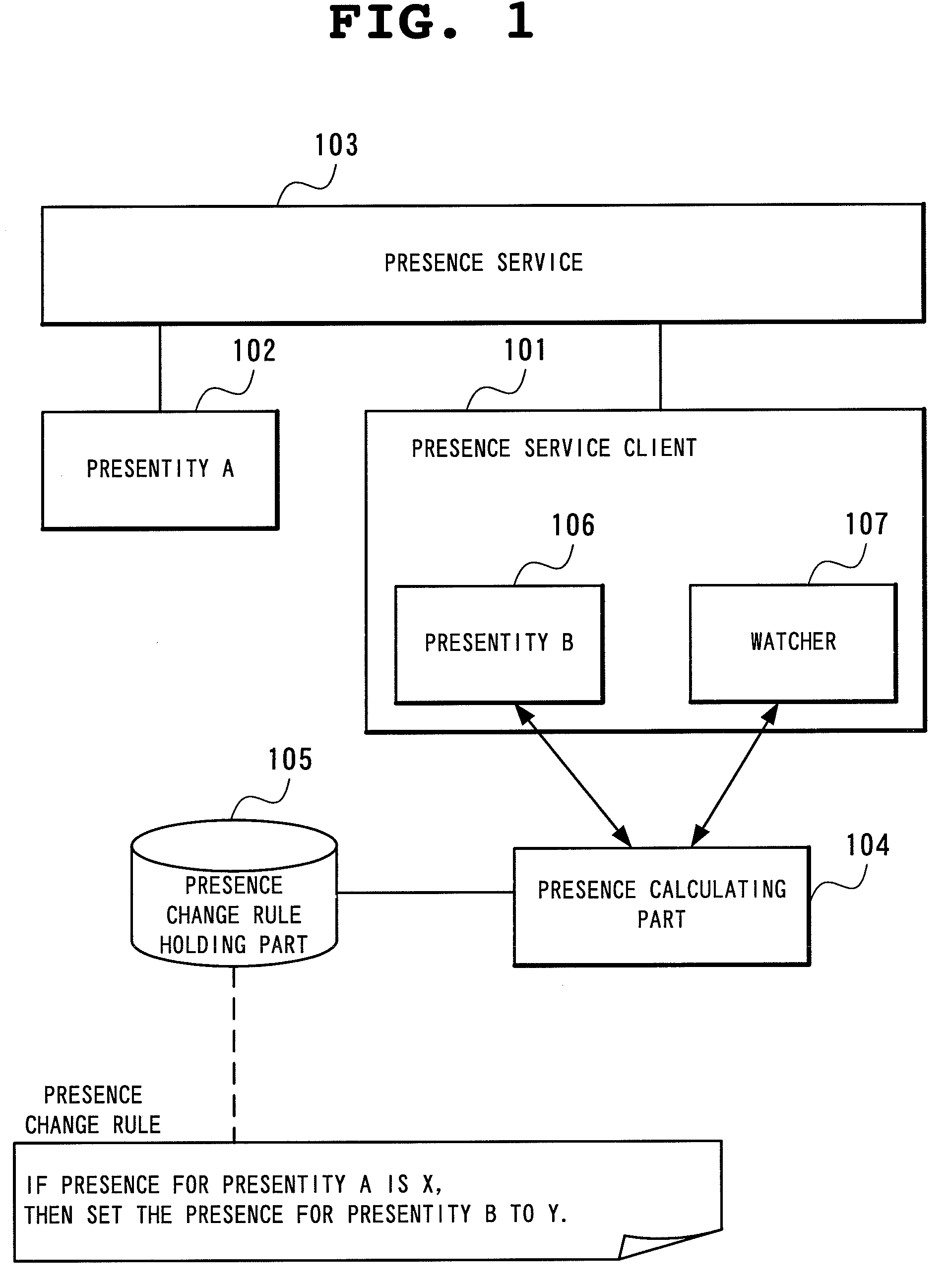
The present invention provides a presence system that can automatically change presence information for a presentity based on changes in other presentities. This allows the presentity to communicate with all the other presentities, even if they are not all actively monitoring the presentity. The system can also generate a buddy list based on the presence information of other presentities and make it easier for users to add new members to the buddy list. The system can also provide dynamic buddy lists based on the presence information of the other presentities. Overall, the invention provides a more efficient and effective way to manage presence information for a presence service client.

Problems solved by technology

Relying on manual setting of these values by users is problematic in terms of the reliability of their presence information, since many users often forget updating their states.
This gives rise to another problem.
Checking the presence information for every member of the group is an unreasonably onerous task for the user because the presence information he or she obtains can be for any member in the group.
Also from the viewpoint of group members, there are privacy-related problems associated with disclosing their presence information unnecessarily to the user.
This entails another problem.
As the user continues to utilize the presence service, the number of communication partners increases, making the task of managing his or her buddy list increasingly burdensome.
If the user wants to observe the states of different partners according to time of day, place and other context, the burden on the user becomes even greater because a buddy list must be prepared for each context.
A static buddy list presents other problems in addition to management burden.
The user is likely to encounter difficulties when preparing such a buddy list, because partners to be included in the private buddy list will stay in the list all the time, regardless of whether they are working or not.
When using a conventional static buddy list, it is impossible for the user to create a state-specific buddy list.
Presently, it is not possible either to create a buddy list by restricting the current states of principals unless the user is aware of their URIs.
The number of taxis cruising in a town is by far too large for the passenger to identify the URI of every applicable taxi.
However, these system do not have a mechanism to retrieve URIs automatically based on a state.
In a conventional presence service as described above, notification of a presence change is sent at a time to all the subscribers that are performing subscription; it is not possible for presentities to perform fine control of destinations of such notification.
For this reason, the conventional presence service may create inconveniences if a certain relationship will occur between a presentity and a subscriber according to the state of the presentity.
There may be certain relationships that a user wants to give higher priority over others in processing, but conventional presence services typically have no mechanism to handle these relationships in a special manner.
Furthermore, there is no mechanism in conventional presence services that allows a presentity to perform context-dependent control of destinations of notification based on its own state, time of day and so on.

Method used


Image

  • Presence system and information processing equipment, dynamic buddy list generation method in presence system, and presence notification destination controlling method and its program for use with presence system
  • Presence system and information processing equipment, dynamic buddy list generation method in presence system, and presence notification destination controlling method and its program for use with presence system
  • Presence system and information processing equipment, dynamic buddy list generation method in presence system, and presence notification destination controlling method and its program for use with presence system

Examples


second embodiment

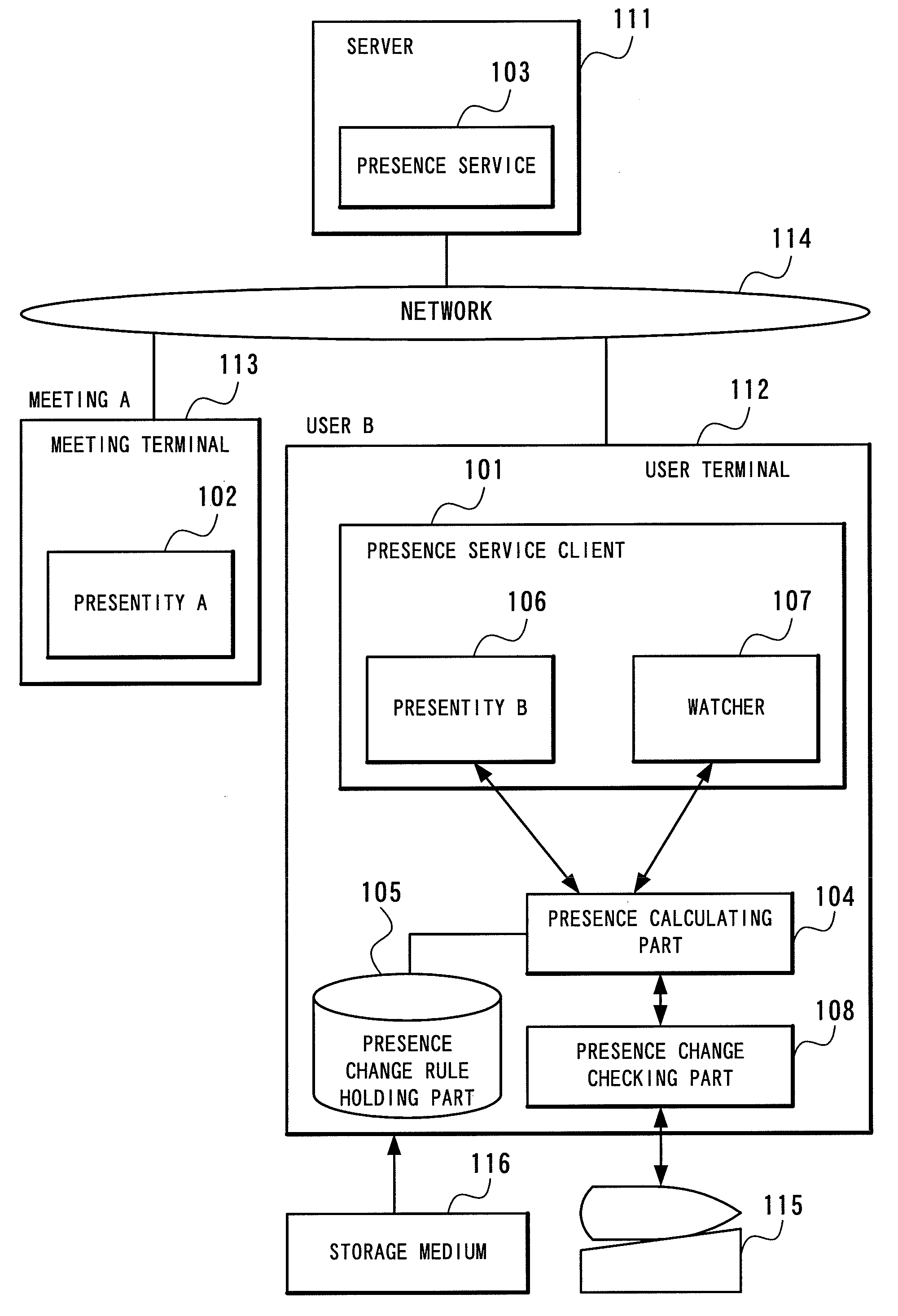
[0088]Reference to FIG. 4 reveals that the presence system according to the second embodiment of the present invention is similar to the first embodiment shown in FIG. 1, except in that the presence calculating part 104 has a presence change checking part 108 connected to it.

[0089]The presence change checking part 108 is a unit for inquiring a user on the presence service client 101 before the presence calculating part 104 issues a change request to the presentity 106 on the presence service client 101, to check if the presence may be changed or not. This inquiry may be made using any method. One possible method is to receive the calculated presence value from the presence calculating part 104 and then to prompt the user to confirm a change to that presence value on the display of the computer incorporating an implementation of the presence service client 101. If the unit receives a response from the user that expressly accepts or rejects the change, and if the response is affirmati...

third embodiment

[0095]As shown in FIG. 6, a presence system according to the third embodiment of the present invention comprises a presence service client 203 associated with a certain Group G; a presence calculating part 204; a presence change rule holding part 205; a group member managing part 206; a member client 208 that includes a presentity 207 for each of the members of said Group G; and a presence service 209.

[0096]The presence service client 203 has a presentity 201 and a watcher 202, and operates as a client for the presence service.

[0097]The presentity 201 provides the presence given by the presence calculating part 204 to the presence service 209 as its own presence.

[0098]For each of the members of Group G given by the group member managing part 206, the watcher 202 acquires the presence for the presentity 207 from the presence service 209 and provides it to the presence calculating part 204. The watcher 202 includes a fetcher and a subscriber. If the presence provided by the presentity...

concrete example 1

[0166]Using Concrete Example 1, the fourth embodiment will further be described, with focus on how the buddy list for User A will change in response to state changes. User A herein corresponds to the principal (305) in FIG. 10.

[0167]In addition to User A, the presence service is participated by many other users (User B, User C, . . . ). These users correspond to the principals (305-i) in FIG. 10. Every user of the presence service has presence information consisting of at least his or her communication state and location. It is possible to monitor (subscribe to) the communication state and location of any user.

[0168]A communication state can take a value of “Online” or “Offline.”“Online” means that the user can answer a phone call, while “Offline” means that user cannot. A location for the purpose of Concrete Example 1 is represented by the name of the nearest station from where the user is actually located. If, for example, “Tokyo” is given as a user's location, it means that Tokyo...


PUM


Abstract

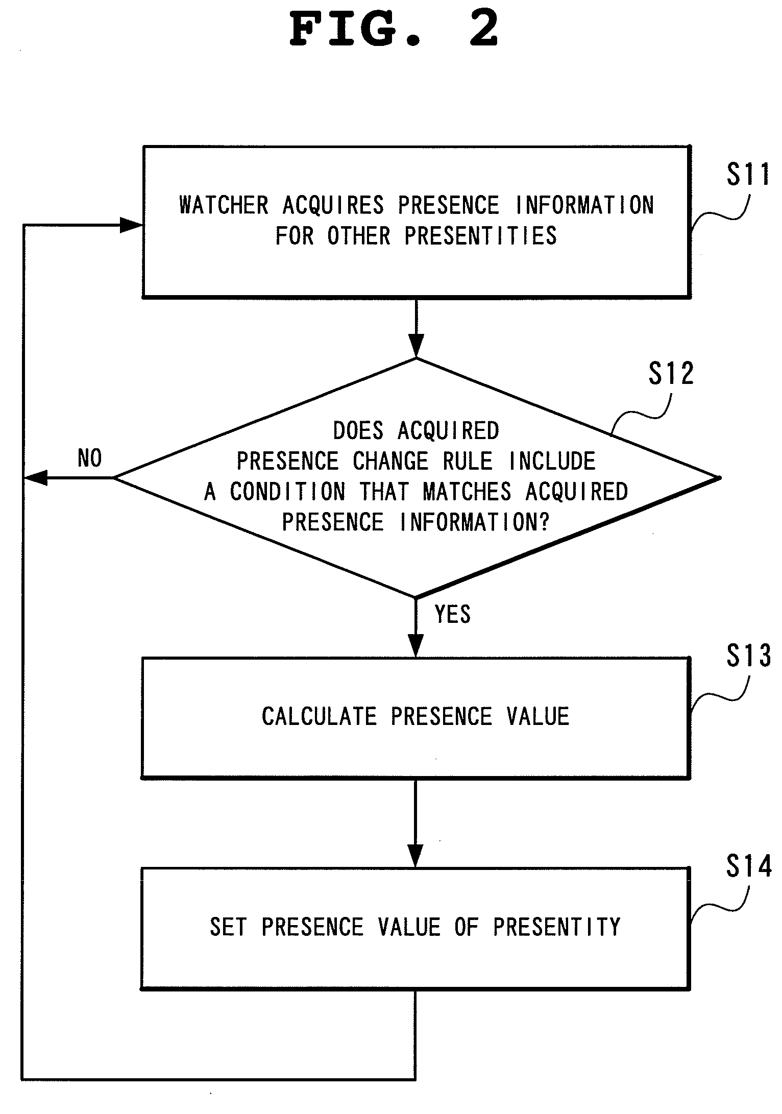
A presentity service client has a presentity that issues presence information to a presence service and a watcher which observes presence information for other presentities; a presence change rule holding part holds a presence change rule; and a presence calculating part changes the presence information for the presentity, using as a trigger a change in presence information of other presentities, based on the presence information of other presentity acquired by the watcher and in accordance with the presence change rule held by a presence change rules holding part.

Description

BACKGROUNDS OF THE INVENTION[0001]This is a Divisional Application of pending prior application Ser. No. 10 / 761,364 filed Jan. 22, 2004 which claims the priority of Japanese Patent Application No. 2003-013137 filed Jan. 22, 2003, Japanese Patent Application No. 2003-019298 filed Jan. 28, 2003 and Japanese Patent Application No. 2003-057895 filed Mar. 5, 2003.FIELD OF THE INVENTION[0002]The present invention relates to a presence system, and more particularly, to a presence system that can change presence information for a presentity automatically by using as a trigger a change occurring in presence information for other presentity. The present invention also relates to a dynamic buddy list generation method in the presence system, and more particularly, to a dynamic buddy list generation method for automatically generating a buddy list in any desired form. Furthermore, the present invention relates to a presence system and a presence notification destination controlling method and i...

Claims


Application Information

Patent Timeline
Patent Type & Authority Applications(United States)
IPC IPC(8): G06F15/16G06F15/173H04L12/58H04L29/06H04L29/08
CPCH04L12/581H04L51/04H04L67/24H04W4/023H04W4/18H04W4/02H04L67/54
Inventor ITO, NAOKOWATANABE, MASAFUMI
Owner NEC CORP
Learn More