
Door stop apparatus

Inactive Publication Date: 2009-06-04
JUNKINS MITCH
View PDF14 Cites 19 Cited by
  • Summary
  • Abstract
  • Description
  • Claims
  • Application Information

AI Technical Summary

Benefits of technology

[0009]Among the many different possibilities contemplated, the apparatus may allow for multiple configurations of the apparatus whereby the door stop may be configured to adapt to a plurality of different doors when desired by a user.
[0040]In yet another exemplary embodiment of the present invention, an apparatus is provided whereby the apparatus requires a minimal tool used to assemble, and / or utilize, and may be easily removed from a door and placed on another door when desired by a user.

Problems solved by technology

The problem with these types of hydraulic arms that close after each use, is that they can be problematic when an individual needs to re-enter a room multiple times. Moreover, they may be much more difficult to open because of the added pressure that it requires to open the door in the first place.
However, one problem with such a device is that they take up considerable room and can be easily moved out of place and thereby not have the desired effect.
For example, if a brick is placed in front of the door to keep it open, it is possible that the brick may be improperly dislodged and thereby allow the door to close.
Additionally, it is entirely foreseeable that an individual may trip on the brick if it is in the path of a walkway or if the individual does not see the device because they are carrying an article or other items that may block their view of the pathway.
In this scenario, the problem is that the object may create a more hazardous situation than it's worth.
However, one problem with this door stop is that if the rubber padding becomes dirty, it loses its ability to maintain traction and thereby the friction will allow the door to close even when it is being utilized properly.
Additional problems with this type of door stop is the need for permanent attachment to the door.

Method used


Image

  • Door stop apparatus
  • Door stop apparatus
  • Door stop apparatus

Examples


Embodiment Construction

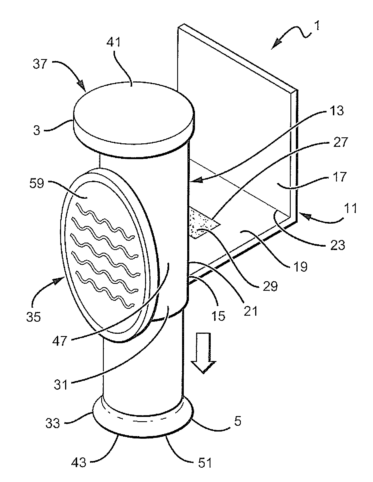
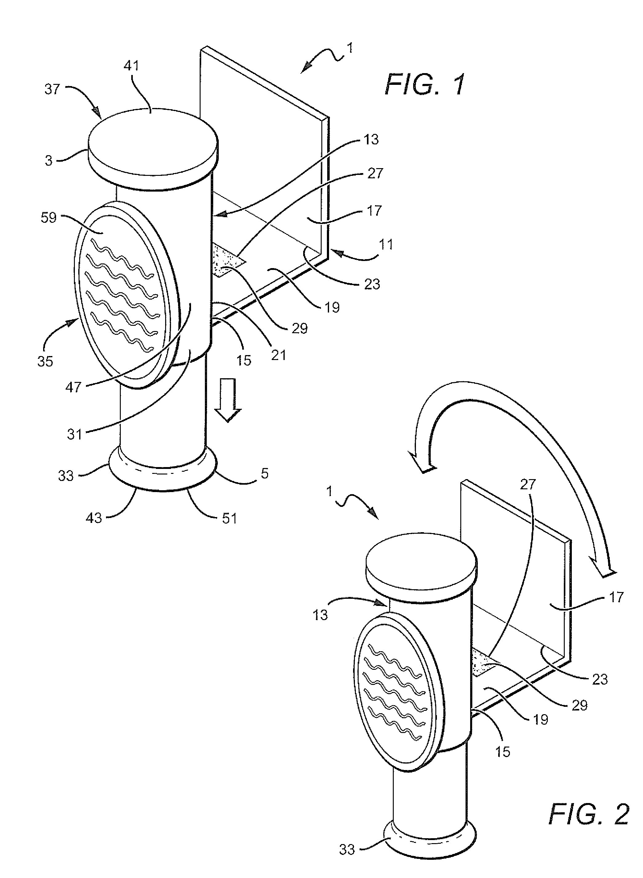
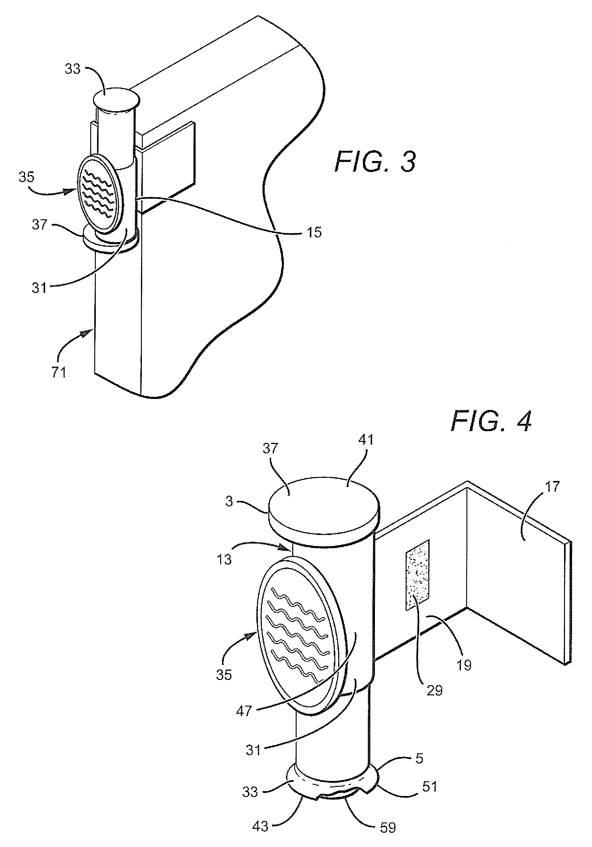
[0046]Referring now to the drawings were like numbers are referenced to describe the invention, a door stop apparatus 1 is illustrated. The door stop apparatus 1 has at least a top portion 3 and a bottom portion 5. The top portion 3 may be oriented such that the top portion is viewable by a user from their vantage point. In an exemplary embodiment the door stop apparatus 1 may be adapted to fit about the bottom portion of a door (see element 71 in FIG. 3). However it should be understood that the door stop apparatus 1 may be utilized on any portion of the door 71 which it may be adapted thereto. In an exemplary embodiment, the door stop apparatus 1 may have a mounting bracket 11 attached to a brake assembly 13. The mounting bracket 11 may have a first side 15 and a second side 17 whereby the first side 15 is adapted to be in close association with the brake assembly 13. Moreover, the first side 15 may be pivotally attached to the brake assembly 13 and may rotate about the brake asse...


PUM


Abstract

An improved door stop apparatus is provided. The improved door stop may have a brake mechanism having a brake portion and a brake release portion. Further, the brake mechanism may also have a magnetic portion that corresponds to a metal piece adhered to a wall for keeping the door ajar when friction and / or traction is not available. Additionally, an improved door stop apparatus is provided whereby the brake portion is adapted to a mounting plate that fits to a door wherein the brake mechanism may rotate about the mounting plate. Moreover, the present invention provides an improved door stop whereby the door stop is adaptable to be removably attached to any door without the need for permanent affixment of the door stop to the door.

Description

PRIORITY CLAIM[0001]This application claims priority to the earlier filed U.S. Provisional Patent Application 60 / 991,657, filed on Nov. 30, 2007 which is hereby incorporated herein by reference in its entirety.FIELD OF THE INVENTION[0002]The field of the invention is for a device to hold a door in a fixed location. More specifically, the field of the invention is for an adaptable door stop apparatus for holding a door open when in use.BACKGROUND[0003]Doorstops are devices that hold a door open, or prevent the door from opening when desired by a user. Since the advent of doors that open and close, there has been a need for a device, object or apparatus that can hold the door open, especially when the door contains some type of hydraulic and / or pneumatic door opener, and / or closer. In most prior art doors, a hydraulic arm is utilized to close the door after entry of an individual into a room, thereby allowing for hands free closing of the door after the individual has utilized the doo...

Claims


Application Information

Patent Timeline
IPC IPC(8): E05F5/02E05F5/10
CPCE05C17/446Y10T16/61Y10T16/62E05C17/54
Inventor JUNKINS, MITCH
Owner JUNKINS MITCH
Learn More