
Mountable linear light welt

The mountable linear light welt with an integrally attached wing member addresses the challenge of securing electroluminescent lighting to surfaces by allowing placement into joint spaces, providing a secure and aesthetically improved mounting solution for electroluminescent lighting products.

Inactive Publication Date: 2009-06-04
BRUCE KEVIN +1
View PDF16 Cites 8 Cited by
  • Summary
  • Abstract
  • Description
  • Claims
  • Application Information

AI Technical Summary

Benefits of technology

Enables easy and aesthetically acceptable mounting of electroluminescent lighting to surfaces or joints, enhancing installation flexibility and appearance.

Problems solved by technology

Because the outer insulation layer is circular in cross section, it is difficult to attached or mount securely to a flat surface or joint.
Typically, clips or adhesives are used to attach the outer insulation layer to a flat surface which is cosmetically unacceptable in some applications.

Method used


Image

  • Mountable linear light welt
  • Mountable linear light welt
  • Mountable linear light welt

Examples


Embodiment Construction

)

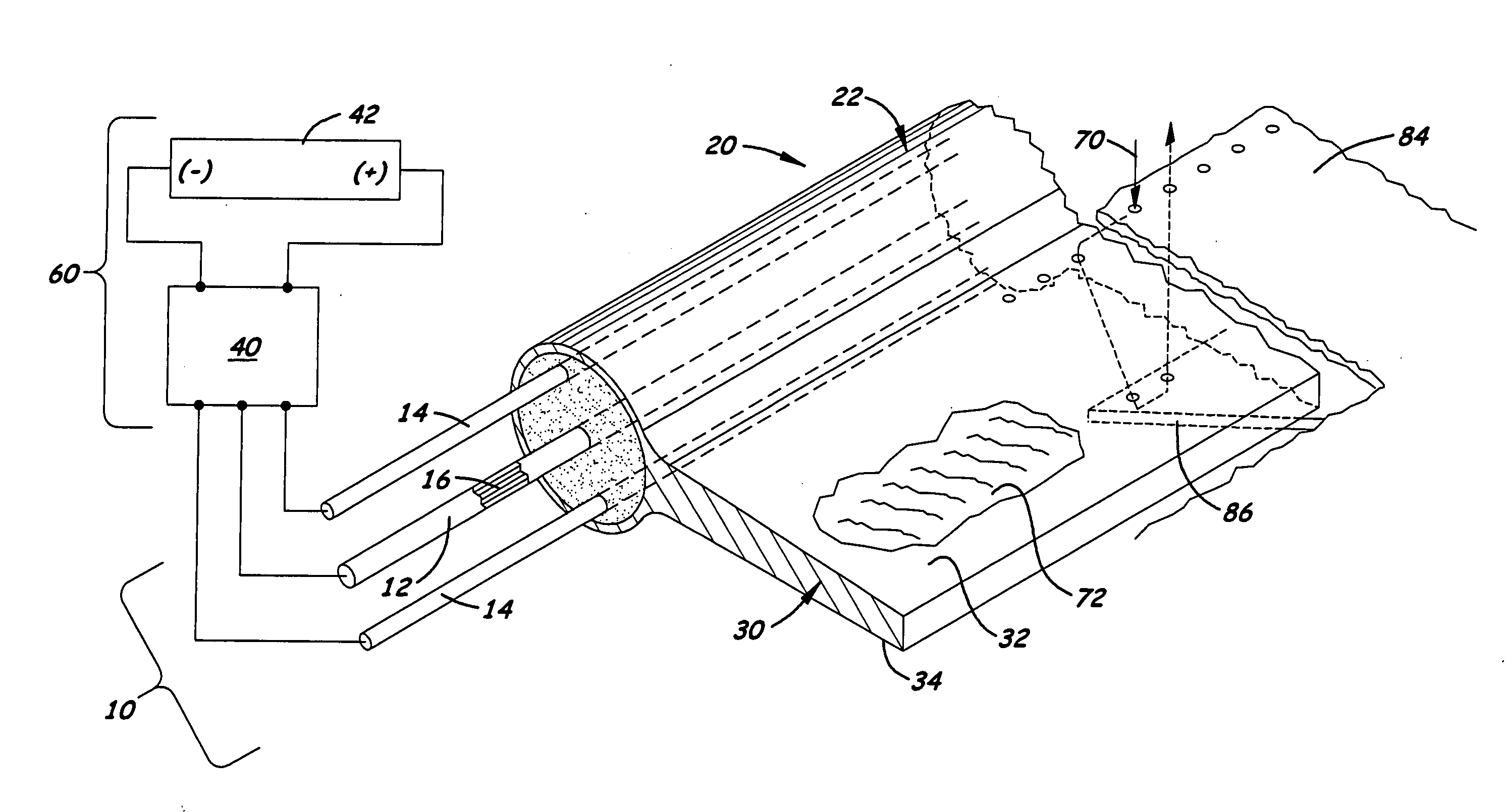
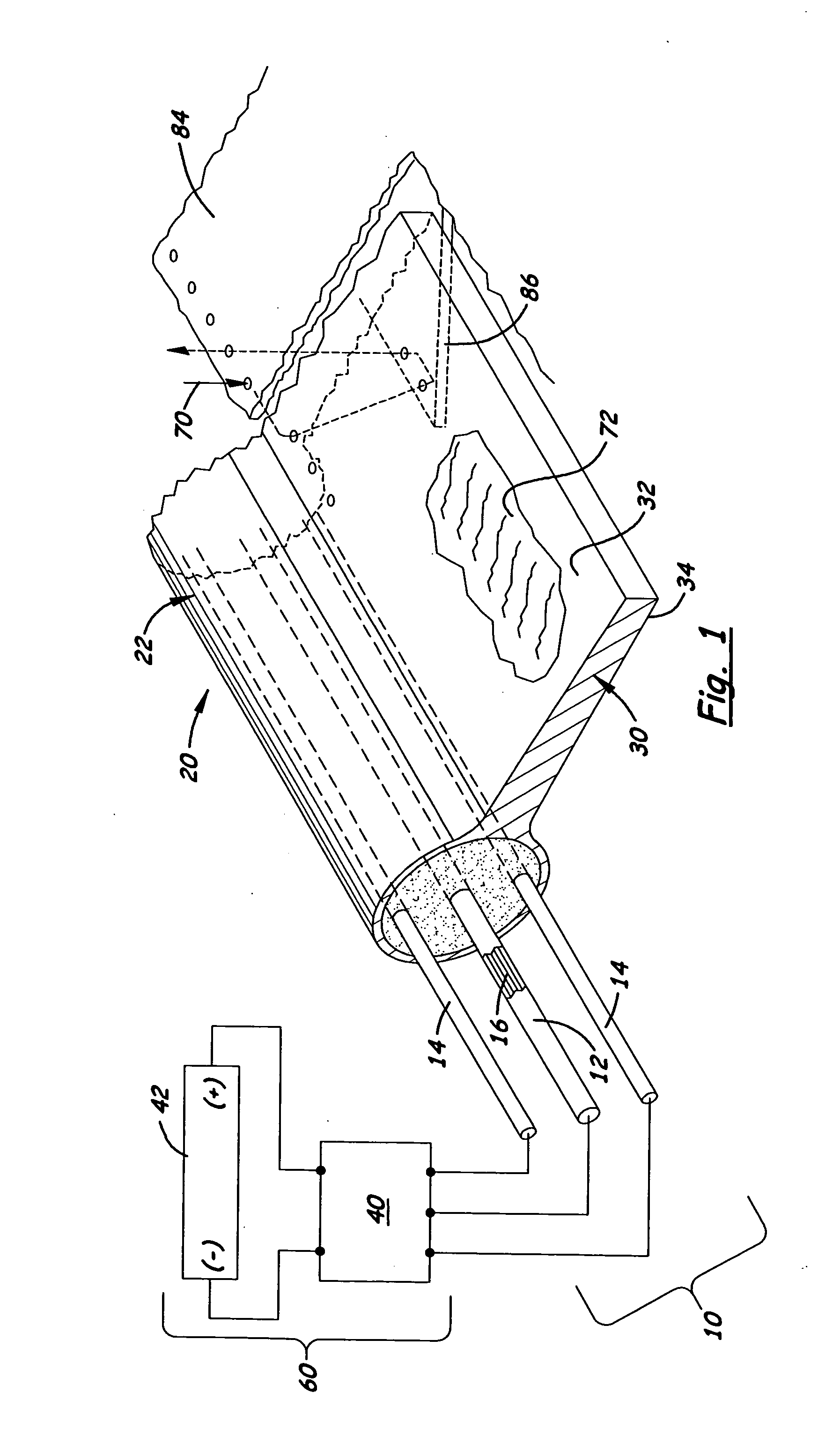
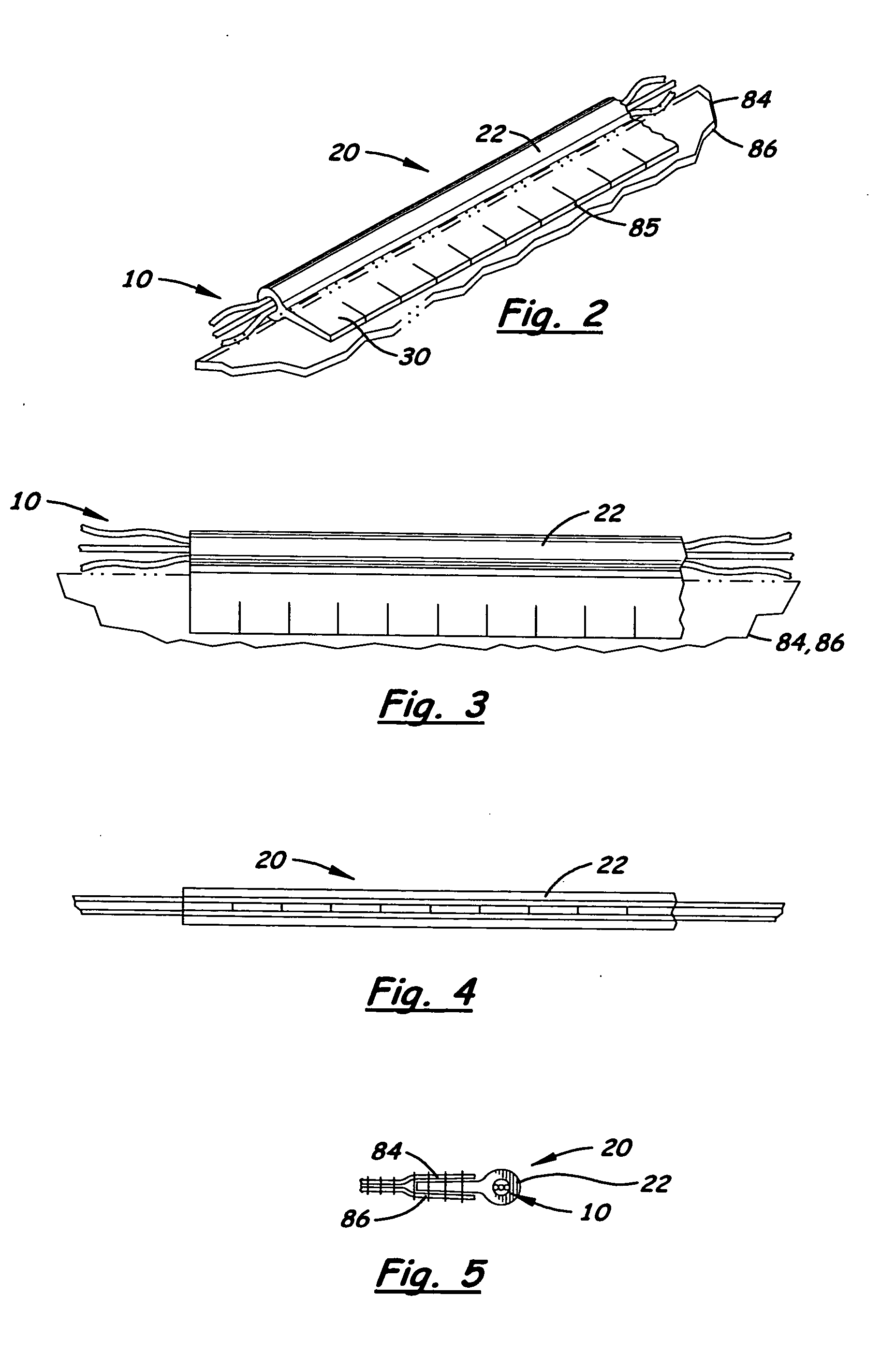
[0017]Shown in the accompanying FIGS. 1-8, is a mountable linear light welt 20 that includes a liner light source which may be an electroluminescent filament 10 with a center conductor 12 and at least one outer conductor 14, with an electroluminescent chemical 16 dispersed over the center conductor 12 that undergoes electroluminescence when excited with by a suitable AC power source 60. In the first embodiment, shown in FIGS. 1-5, the welt 20 includes a transparent or semi-transparent sheath casing 22 which is circular or oval in cross-section and designed to contain the electroluminescent filament 10. Integrally formed, laterally extending from the casing 22 is wing member 30. The wing member 30 is a relatively thin structure that extends longitudinally over a portion or the entire length of the outer casing 22. In the preferred embodiment, the top and bottom outer edges, 32, 34, respectively, of the wing member 30 converge towards their outer edges thereby enabling the wing membe...


PUM


Abstract

A mountable welt that is easier to attach to a desired surface or joint. The welt includes a transparent or semi-transparent sheath casing circular or oval in cross-section with at least one integrally formed, laterally extending wing member. The wing member is a relatively thin structure that extends longitudinally over a portion or the entire length of the outer casing. In the preferred embodiment, the outer edges of the wing member is converge are converged towards their outer edges thereby enabling the wing to be placed into a joint space. A suitable attachment means, such as sewing, an adhesive, or a closed joint, may be used to attach the wing to the desired surface or joint while allowing the outer casing to be exposed. Located inside the outer sheath is a continuous linear light.

Description

[0001]This is a continuation application based on utility patent application (Ser. No. 10 / 152,364), filed May 20, 2002 now U.S. Pat. No. 7,425,079 and design patent application (Ser. No. 29 / 138,485) filed on Mar. 12, 2001, now U.S. Pat. No. D 457,299BACKGROUND OF THE INVENTION[0002]1. Field of the Invention[0003]The present invention relates to flexible, tubular light sources and, more particularly to such products that can be easily mounted to a surface.[0004]2. Description of the Related Art[0005]Electroluminescence is the conversion of electrical energy into light by the activation of a phosphor layer by an alternating electrical current. Electroluminescent lighting consists of a layer of phosphor placed between two thin conductors which, when applied to a 400 to 2000 Hz AC circuit cause the layer of phosphor to rapidly charge and discharge and emit light. Dyes and filters are mixed or added to the electroluminescent lighting to emit specific colors. Also, inverters may be used t...

Claims


Application Information

Patent Timeline
Patent Type & Authority Applications(United States)
IPC IPC(8): F21V9/16F21V21/00H05B33/02
CPCH05B33/02Y10T428/239Y10T428/24008Y10T428/2973
Inventor BRUCE, KEVINLORCA-MERONO, LUIS
Owner BRUCE KEVIN
Learn More