Homogenisation valve

Active Publication Date: 2009-06-04
AECI LTD
View PDF14 Cites 29 Cited by
  • Summary
  • Abstract
  • Description
  • Claims
  • Application Information

AI Technical Summary

Benefits of technology

[0008]It is accordingly an object of the invention to provide a homogenisation valve

Problems solved by technology

Homogenisation is therefore n

Method used


Image

  • Homogenisation valve
  • Homogenisation valve
  • Homogenisation valve

Examples


Embodiment Construction

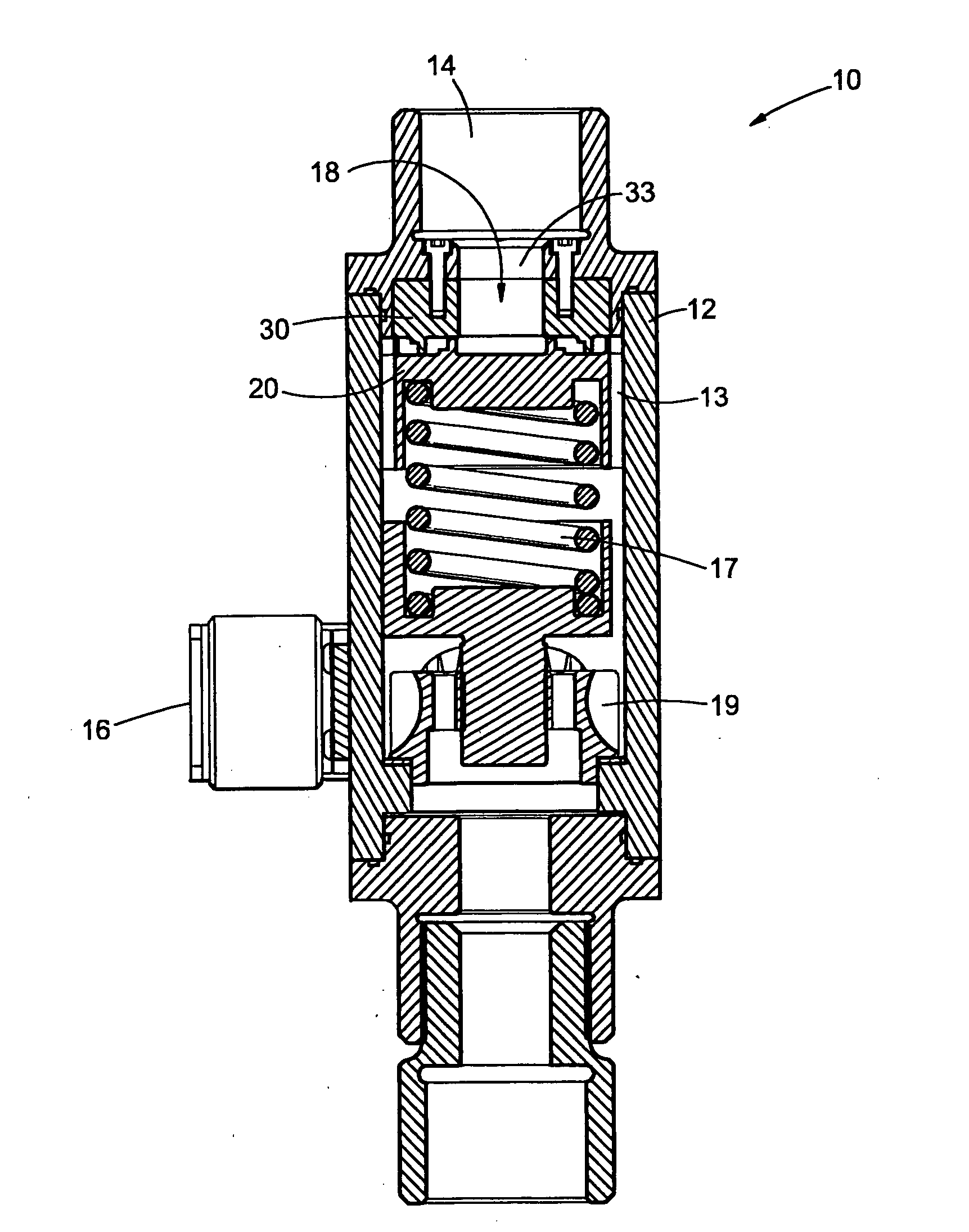
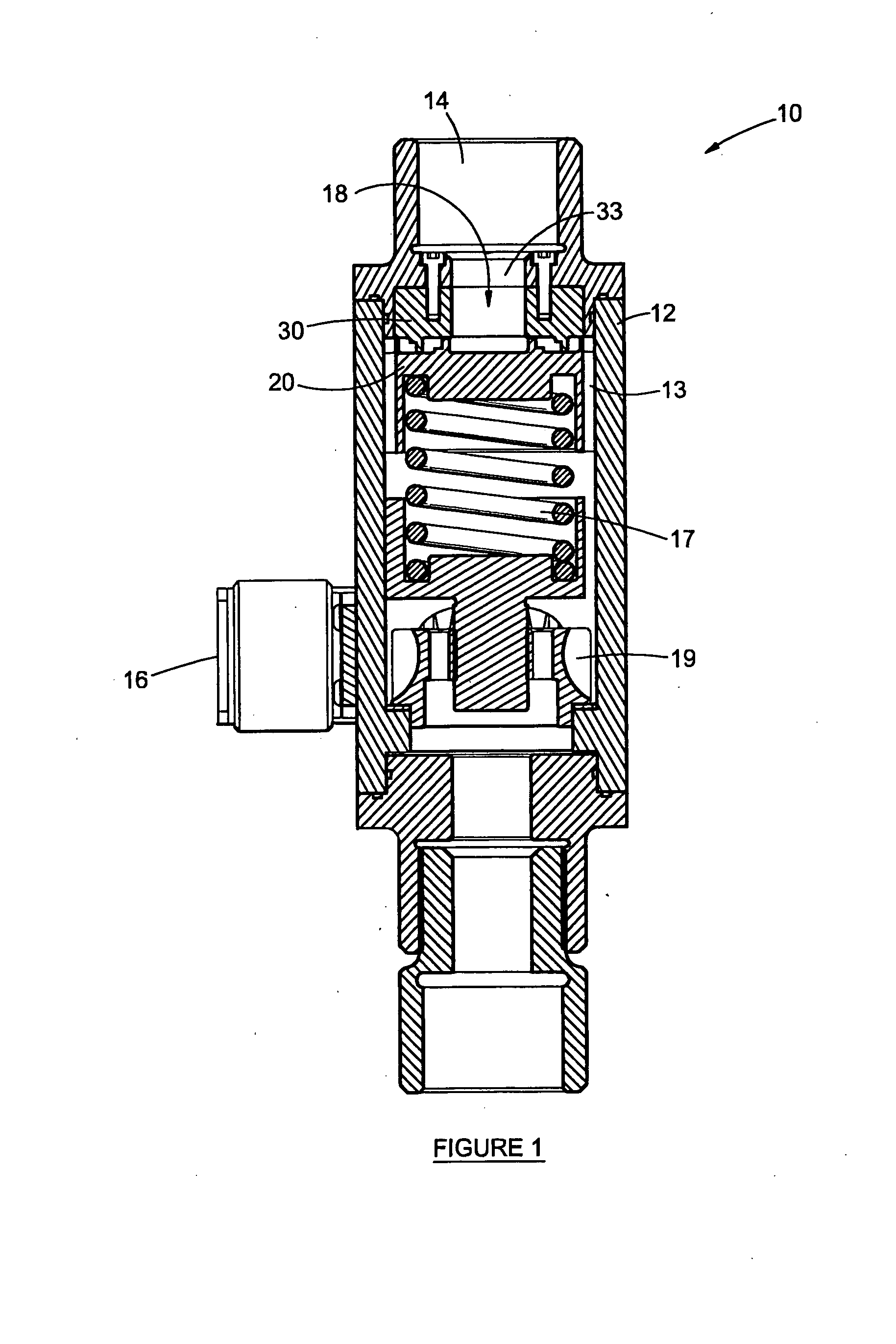
[0044]Referring to the figures, in which like numerals indicate like features, a non-limiting example of a homogenisation device, in the form of a homogenising valve, in accordance with the invention is generally indicated by reference numeral 10. The homogenisation valve 10, as shown in FIG. 1, includes a valve body 12 having an inlet 14, an outlet 16 and a flow passage therebetween. An internal valve assembly 18 comprising a plug 20 and a seat 30 is located in the flow passage. The homogenisation valve 10 also include biasing means 17 in the form of a helical spring for biasing the plug 20 towards the seat 30 as described in more detail hereinbelow. The magnitude of the bias exerted by the biasing means can be adjusted by means of adjustment means 19.

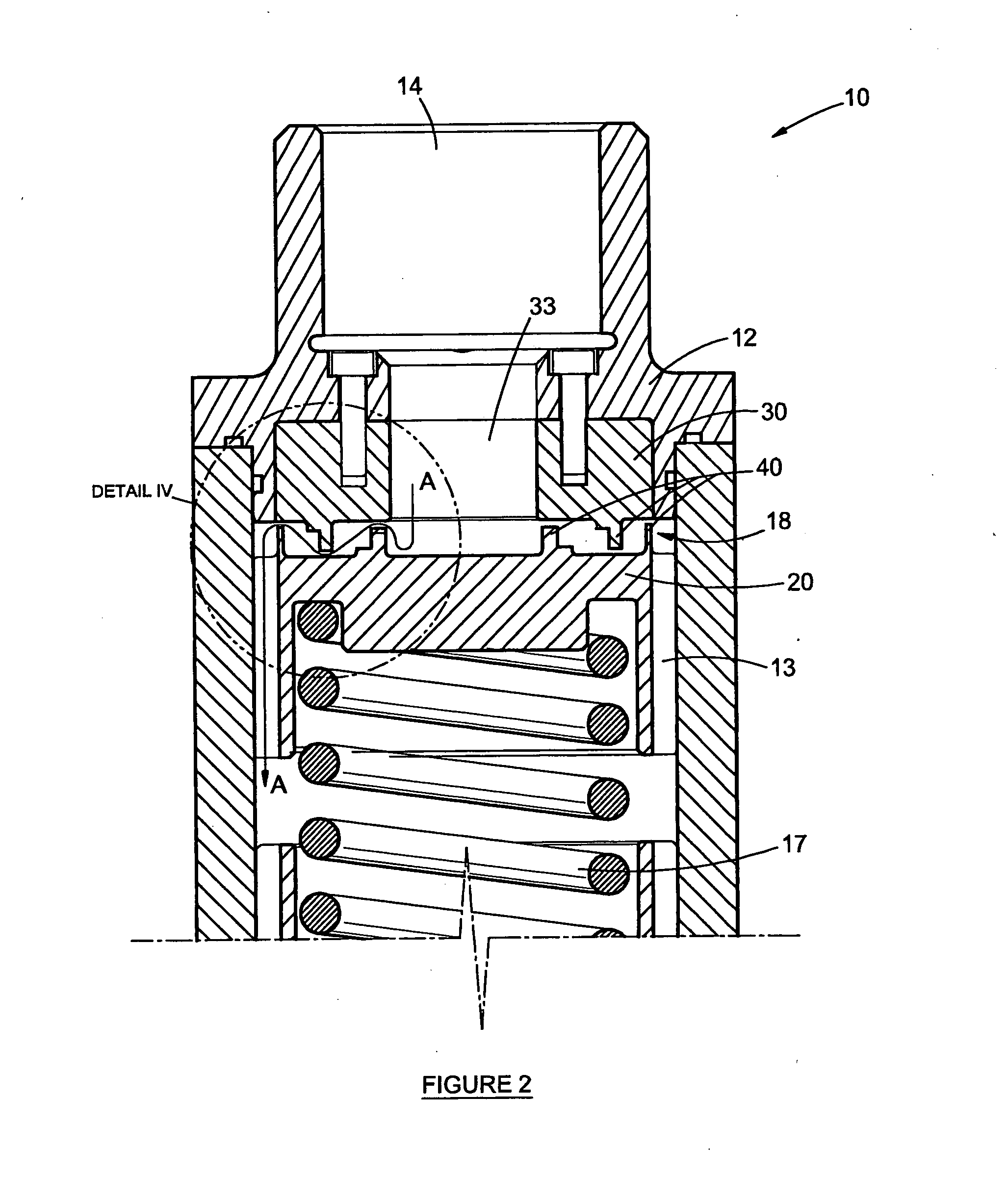
[0045]FIG. 2 shows the upper part of the homogenisation valve 10 in more detail. The seat 30 is stationary mounted to the valve body 12, and the inlet 14 to the valve 10 is in flow communication with an inlet passage 33 in the centre ...


PUM

PropertyMeasurementUnit
Flow rateaaaaaaaaaa
Diameteraaaaaaaaaa
Electrical resistanceaaaaaaaaaa

Abstract

The invention relates to an improved homogenization valve, and more particularly, but not exclusively, to a homogenization valve for use in homogenizing emulsion explosives. The homogenization device comprises a body having a flow passage therethrough, opposing first and second homogenization members located in the flow passage; the homogenization members having opposing homogenization surfaces that form a flow restriction of the flow passage therebetween. At least one of the homogenization surfaces has a flow resistance being suitable to cause at least part of the flow passing through the flow restriction to be diverged in a non-linear path across the homogenization surface.

Description

FIELD OF THE INVENTION[0001]The invention relates to an improved homogenisation valve, and more particularly, but not exclusively, to a homogenisation valve for use in homogenising emulsion explosives.BACKGROUND TO THE INVENTION[0002]Homogenisation is the process of obtaining a uniform composition and stable structure throughout a fluid comprising more than one phase by subjecting the fluid to a fluid mechanical process that involves the subdivision of particles or droplets into small sizes so as to create a dispersion or emulsion.[0003]Homogenising devices, including homogenisation valves suitable for homogenising emulsions, are well know in industry. In essence a homogenisation valve comprises a valve body in which a stationary seat and a spring-loaded plug is located. The plug is biased towards a closed position in which the plug abuts the seat. The plug and / or the seat typically include at least one annular protrusion that abuts the corresponding seat and / or plug, thus forming a...

Claims


Application Information

Patent Timeline
IPC IPC(8): B01F5/08B01F25/46
CPCB01F3/0807B01F5/0663F16K1/42B01F2215/0057F16K1/36B01F5/0681B01F23/41B01F25/4412B01F25/4423B01F2101/34
Inventor BOER, WILLEM GEORGESANDERS, GRAHAM INNES
Owner AECI LTD
Why Eureka
Try Eureka