Steering Column Assembly

a technology of steering column and assembly, which is applied in the direction of rod connection, mechanical equipment, transportation and packaging, etc., can solve the problems of steering column assembly damage, and needing a costly replacement at parts

Active Publication Date: 2009-06-11
TRW LIMITED
View PDF3 Cites 33 Cited by
  • Summary
  • Abstract
  • Description
  • Claims
  • Application Information

AI Technical Summary

Benefits of technology

[0026]Alternatively, the clamp pin may pass through a slot in the bracket rather than the rail. This in effect gives the same functionality as putting the groove in the bracket ...

Problems solved by technology

A problem may arise, though, if a vehicle manufacture specifies an unusually low breakaway force threshold; e.g. 3000N (in the clamped condition).
In this event, the remaining breakaway resistance still present when the column is unclamped will only be 1500N (i.e. 3000-1500) and this will be insufficient to ensure that the Capsules are not fractured, and the crash stroke is not initiated, by abuse loa...

Method used


Image

  • Steering Column Assembly
  • Steering Column Assembly
  • Steering Column Assembly

Examples


Embodiment Construction

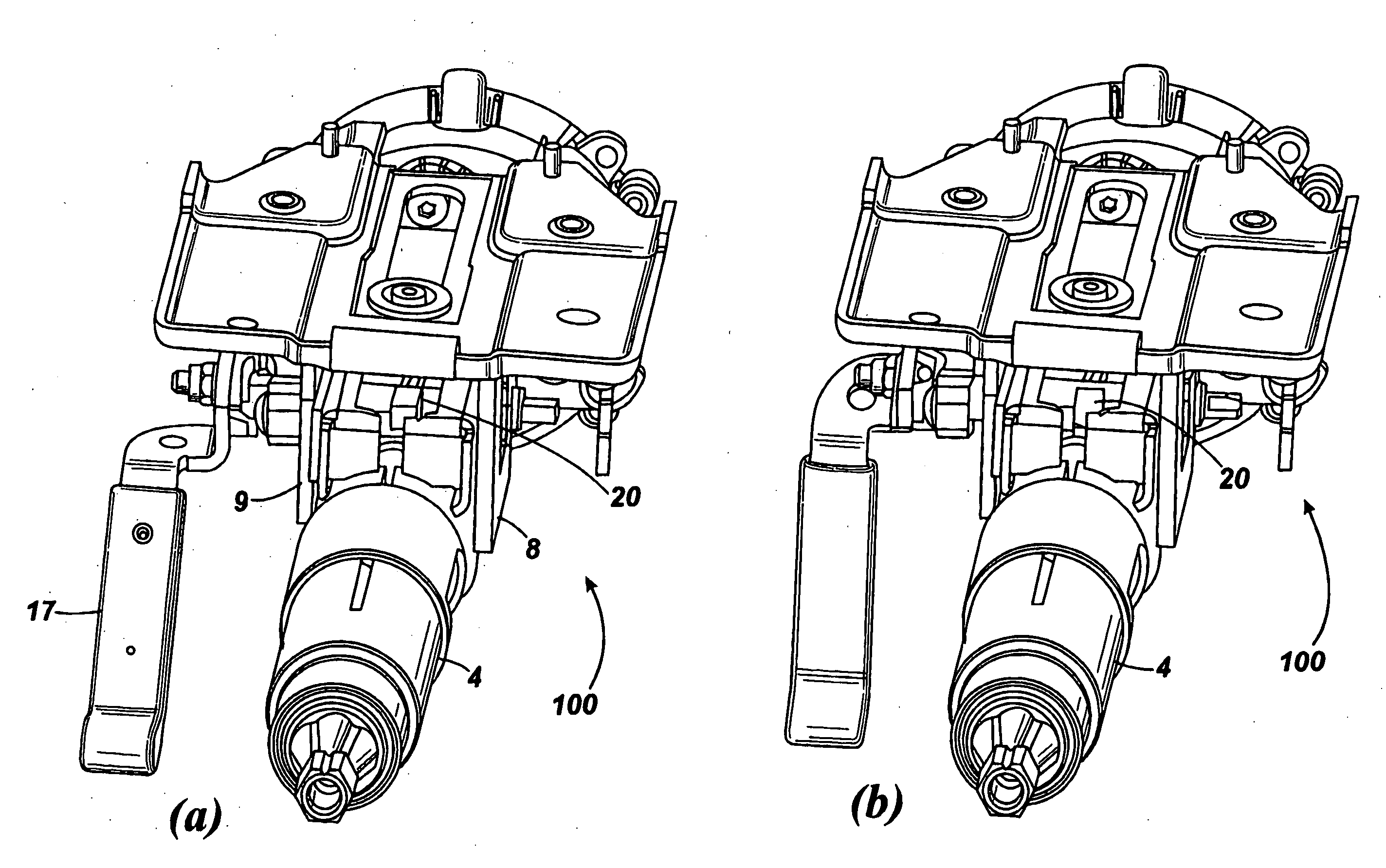
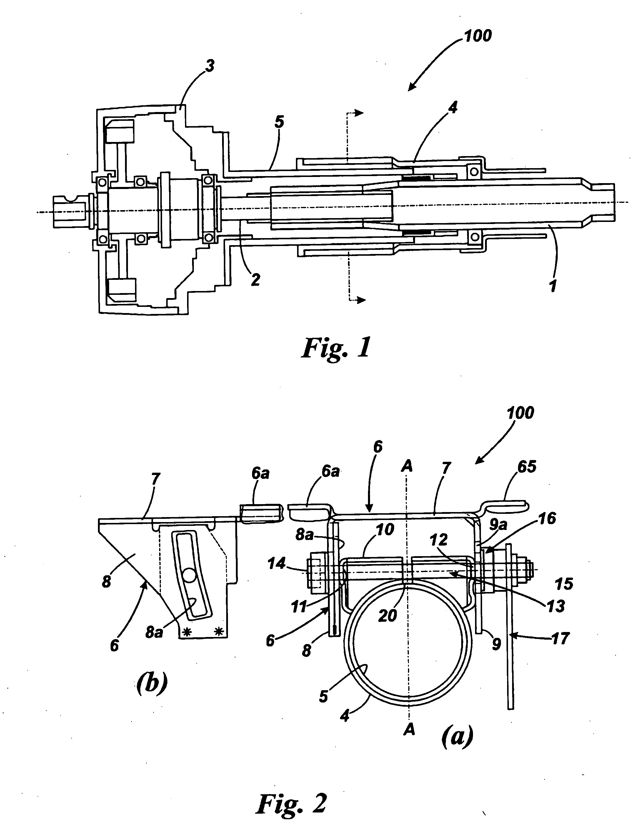
[0040]As shown in FIG. 1, a reach adjustable steering column assembly 100 comprises a two part steering shaft 1, 2 that is located by upper and lower bearings within a telescopic steering column shroud. The shaft 1, 2 connects a steering wheel (not shown) to a part of the steering gear. In the embodiment shown it in fact connects to the steering rack and a gearbox located within a gearbox housing 3 which provides power assistance.

[0041]The shroud comprises an upper shroud portion 4 and a lower shroud portion 5. Both portions are tubular, with the upper shroud portion in this embodiment having a larger internal diameter than the external diameter of the lower shroud portion 5. One end of the upper portion 4 is located concentrically around the top end of the lower shroud portion 5.

[0042]The lower shroud portion 5 is secured to the gearbox housing 3, which is in turn pivotally fixed to a rigid part of the vehicle body. This could, for example, be part of the vehicle bulkhead. The pivo...


PUM


Abstract

A steering column assembly having an adjustable shroud comprises a fixed portion arranged to be secured to a body of a vehicle and a moving portion which can be moved telescopically relative to the fixed portion, a clamp mechanism which releasably fixes the moving portion in position relative the vehicle body, the clamp mechanism being movable between a first, unclamped, position in which the fixed portion and the moving portion can move relative to one another and a second, clamped, position in which the fixed portion and the moving portion are prevented from relative movement, and a lock mechanism, wherein the assembly is so arranged that when the clamp mechanism is in the first position the lock mechanism limits a range of movement of the moving portion relative to the fixed portion at least in a collapse direction by providing a path for collapse forces from the moving portion through the lock mechanism to the fixed portion, and when the clamp mechanism is in the second position the lock mechanism permits additional telescopic movement of the moving portion towards the fixed portion beyond the limited range of movement by removing the force path.

Description

CROSS-REFERENCE TO RELATED APPLICATION[0001]This application claims priority to Great Britain Patent Application No. 0721238.4 filed Oct. 30, 2007, the disclosures of which are incorporated herein by reference in entirety.BACKGROUND OF THE INVENTION[0002]This invention relates to steering column assemblies and in particular to steering column assemblies that are adjustable for reach.[0003]It is known to provide steering columns that adjust for reach. Typically, they comprise a two part steering shaft that can be adjusted in length by one part telescoping over the other. To hold the shaft at the desired length it is known to provide a telescopic steering column shroud that comprises a fixed shroud portion that is secured to a part of the vehicle and a moving shroud portion that can move relative to the fixed part to vary the overall length of the shroud. Bearings within the shroud portions support the steering shaft whilst allowing it to rotate. Typically the two portions comprise tu...

Claims


Application Information

Patent Timeline
IPC IPC(8): B62D1/184
CPCB62D1/184B62D1/195B62D1/192F16B7/1454
Inventor DAVIES, NICLASTHOMPSON, CARL
Owner TRW LIMITED
Why Eureka
Try Eureka