
Wheelchair

a technology for wheelchairs and wheelchairs, applied in the field of wheelchairs, can solve the problems of user inability to easily alter the selected configuration, user's weight, and user's inability to use, and achieve the effects of convenient and efficient self-propulsion, constant knee height position, and convenient access

Active Publication Date: 2009-06-11
BORISOFF JAIMIE
View PDF99 Cites 19 Cited by
  • Summary
  • Abstract
  • Description
  • Claims
  • Application Information

AI Technical Summary

Benefits of technology

[0007]It is therefore an object of the invention to provide a manual wheelchair that enables a user to easily and efficiently self-propel, as well as to dynamically adjust the seat height of the wheelchair to accommodate various situations. It is also desirable that the mechanism that lowers the wheelchair seat results in a relatively constant knee height position, for instance to facilitate access under table tops or sinks. Furthermore, it is desirable to provide a wheelchair that can keep its backrest at a relatively constant angle to the wheelchair frame at all angles of the seat bottom, and to provide a wheelchair that can absorb the shocks encountered during wheelchair travel, as well as allow the user to easily change the seat height without having to leave the chair.
[0009]According to one aspect of the invention there is provided a wheelchair comprising: a frame having a front portion with a seat hinge mounted thereto at a first elevation, and a rear portion rotatably coupled to left and right wheels; and a seat assembly comprising at least one side member hingedly coupled to the seat hinge, and a seat back hingedly coupled to the side member such that the seat back can be maintained at a constant angle relative to the frame when the side member pivots about the seat hinge and moves the seat assembly between multiple elevations. The wheelchair also comprises a lockable spring hingedly mounted to the frame and to the seat assembly; the spring is lockable at multiple positions thereby locking the seat assembly at the multiple elevations. This spring can be sufficiently elastic to suspend the seat assembly and absorb shock at each of the locked multiple elevations.

Problems solved by technology

However, current state of the art chairs still suffer from the problem that once they are set up with a certain configuration, the user cannot easily alter the selected configuration.
For example, ultra-lightweight chairs in particular do not let the user dynamically (in real-time) change their seating position without getting out of the chair to reconfigure the chair's configuration.
The drawback to this position is that it can become uncomfortable over a long period of time and the user is at an even lower position, which entails all the negative issues associated with being ‘short’.
However, these chairs suffer a major drawback in that they tend to be heavier than ultralight chairs as a result of incorporating the numerous mechanisms required to lift the user to a standing height.
Furthermore, the complex mechanisms interfere with the seat's ability to lower to a sufficient low position that enables comfortable and efficient self propulsion.
Typically the tilting operation is operated by an attendant due to the high level of disability of the user.
A disadvantage of this approach is that a user's knees move upwards as the seat is tilted which may prevent a user from fitting their legs under a table when tilted.
Due to their specific design criteria, these chairs also may not provide positive tilt above the horizontal.
As well the backrest assembly tilts with the seat which may inhibit the user from achieving efficient wheeling power when the seat is tilted below the horizontal.

Method used


Image

  • Wheelchair
  • Wheelchair
  • Wheelchair

Examples


Embodiment Construction

[0021]Directional terms such as “left”, “right”, “horizontal”, “vertical”, “transverse” and “longitudinal” are used in this description merely to assist the reader to understand the described embodiments and are not to be construed to limit the orientation of any described method, product, apparatus or parts thereof, in operation or in connection to another object.

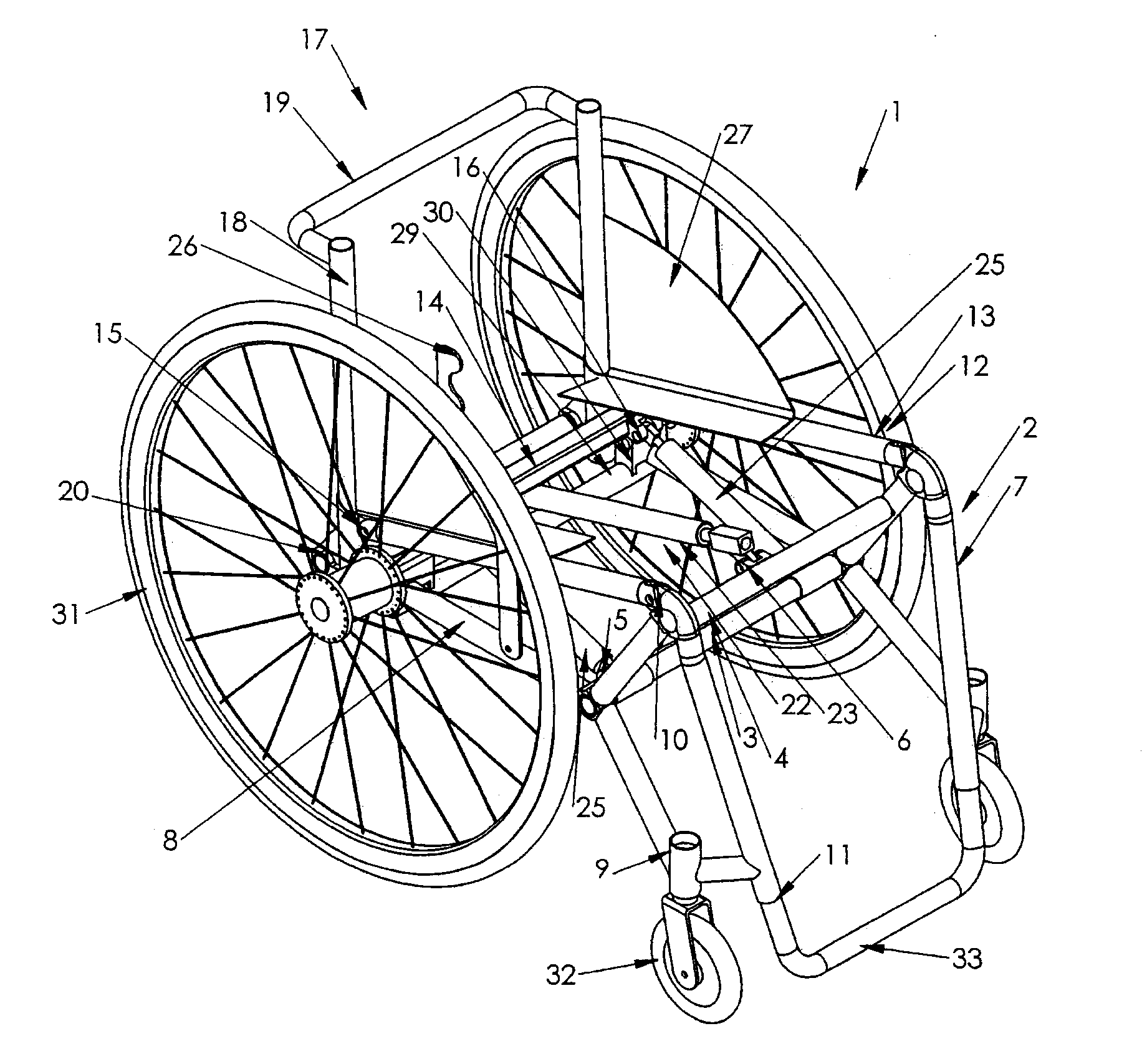
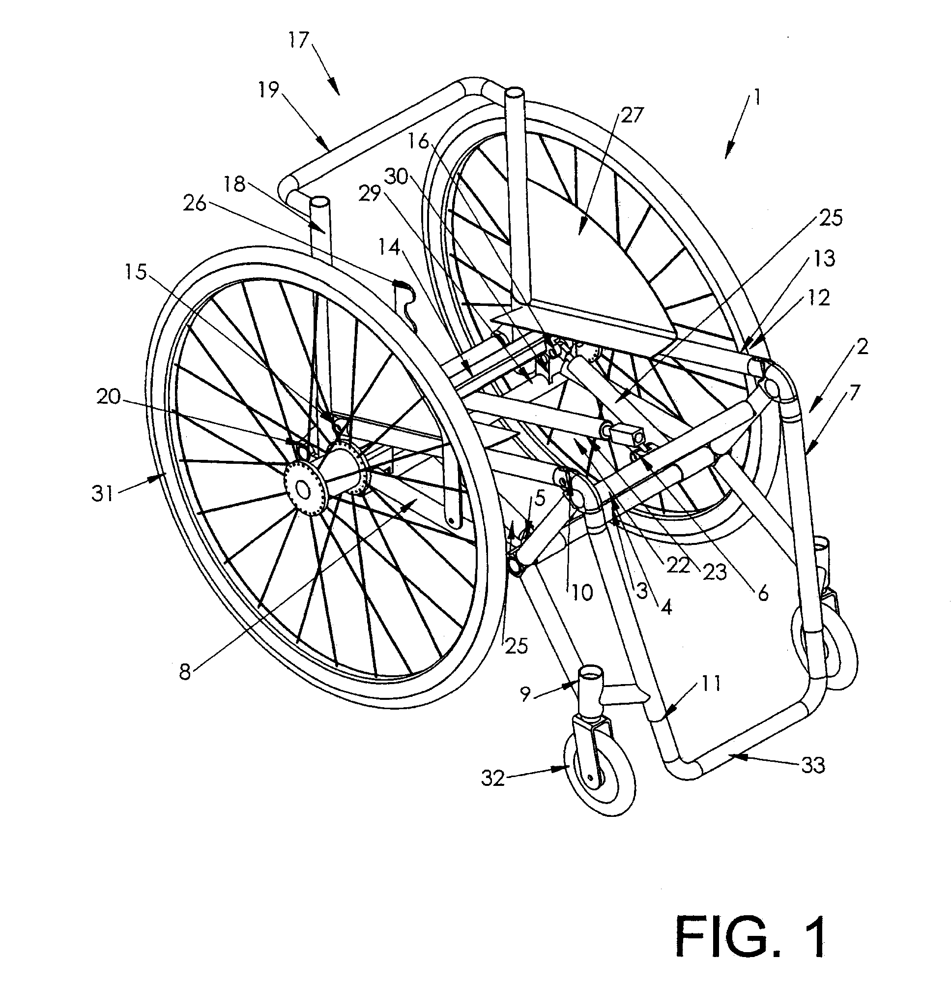
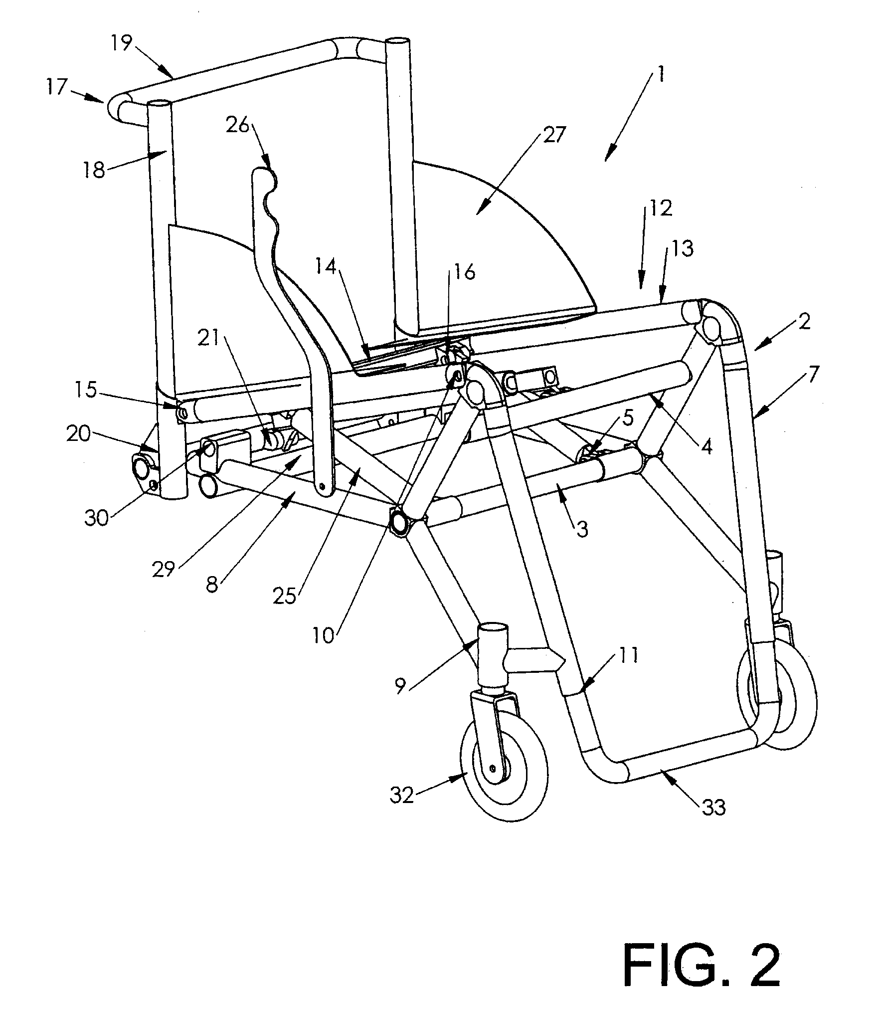
[0022]Referring to FIGS. 1 to 5 and according to one embodiment of the invention, a wheelchair 1 is provided having a seat assembly 12 having a front end that is pivotably coupled to a wheelchair frame 2 such that the seat assembly 12 height is adjustable relative to the frame 2. The seat assembly 12 is suspended by a pair of gas springs 25 which are adjustable to adjust the seat assembly 12 height relative to the frame 2 as well as to serve as shock absorbers to cushion a user during wheelchair travel.

[0023]Referring particularly to FIGS. 2 and 3, the frame 2 comprises a transversely-extending middle cross member 3 and a ...


PUM


Abstract

A wheelchair according to one embodiment is provided with a frame and a seat assembly that is movable in elevation relative to the frame. The frame has a seat hinge mounted thereto, and is rotatably coupled to left and right wheels. The seat assembly has a side member hingedly coupled to the seat hinge and a seat back hingedly coupled to the side member such that the seat back can be maintained at a constant angle relative to the frame when the side member pivots about the seat hinge and moves the seat assembly between multiple elevations. The wheelchair also comprises a lockable spring hingedly mounted to the frame and to the seat assembly; the spring is lockable at multiple positions thereby locking the seat assembly at the multiple elevations. This spring can be sufficiently elastic to suspend the seat assembly and absorb shock at each of the locked multiple elevations.

Description

FIELD OF THE INVENTION[0001]This invention relates generally to wheelchairs, and in particular to a wheelchair with a height adjustable seat.BACKGROUND OF THE INVENTION[0002]Manual wheelchair technology has greatly improved over the last 100 plus years such that many existing wheelchairs on the market today provide a very functional mobility device for active independent individuals with disability. One class of wheelchair, known as “ultra-lightweight” wheelchairs, are very light and enable a user to efficiently self-propel as well as to easily manipulate the wheelchair, e.g. to lift the wheelchair into a car. Many of these types of wheelchairs are engineered with a minimal number of components to keep weight down; such a design also has the added benefit of minimizing the visual impact of the wheelchair, thus focussing the attention of others to the user instead of the wheelchair.[0003]The technology improvements that have led to ultra-lightweight and other types of wheelchairs hav...

Claims


Application Information

Patent Timeline
Patent Type & Authority Applications(United States)
IPC IPC(8): B62M1/14
CPCA61G5/02A61G5/14A61G5/1075A61G5/1059
Inventor BORISOFF, JAIMIE
Owner BORISOFF JAIMIE
Learn More