
Structure for vehicle body lower portion

a technology for vehicle body and lower portion, which is applied in the direction of roof, vehicle sub-unit features, electric propulsion mounting, etc., can solve the problems of increasing achieve the effect of suppressing an increase in the weight of the vehicle body, constant height position, and reliable and efficient protection of the battery

Active Publication Date: 2013-05-16
NISSAN MOTOR CO LTD
View PDF2 Cites 19 Cited by
  • Summary
  • Abstract
  • Description
  • Claims
  • Application Information

AI Technical Summary

Benefits of technology

The invention provides a structure for protecting a battery in a vehicle body when a load is inputted from the side. The structure includes a side member that maintains a constant height position when a load is applied. This helps prevent damage to the battery while keeping the vehicle body's weight down.

Problems solved by technology

However, the above-described conventional vehicle body structure needs to increase plate thickness of the transmission links in order to reliably protect the battery when a load is inputted to the vehicle from a lateral side, and may therefore cause an increase in weight of the vehicle body.

Method used


Image

  • Structure for vehicle body lower portion
  • Structure for vehicle body lower portion
  • Structure for vehicle body lower portion

Examples


Embodiment Construction

[0012]An embodiment of the present invention will be described below in detail with reference to the drawings.

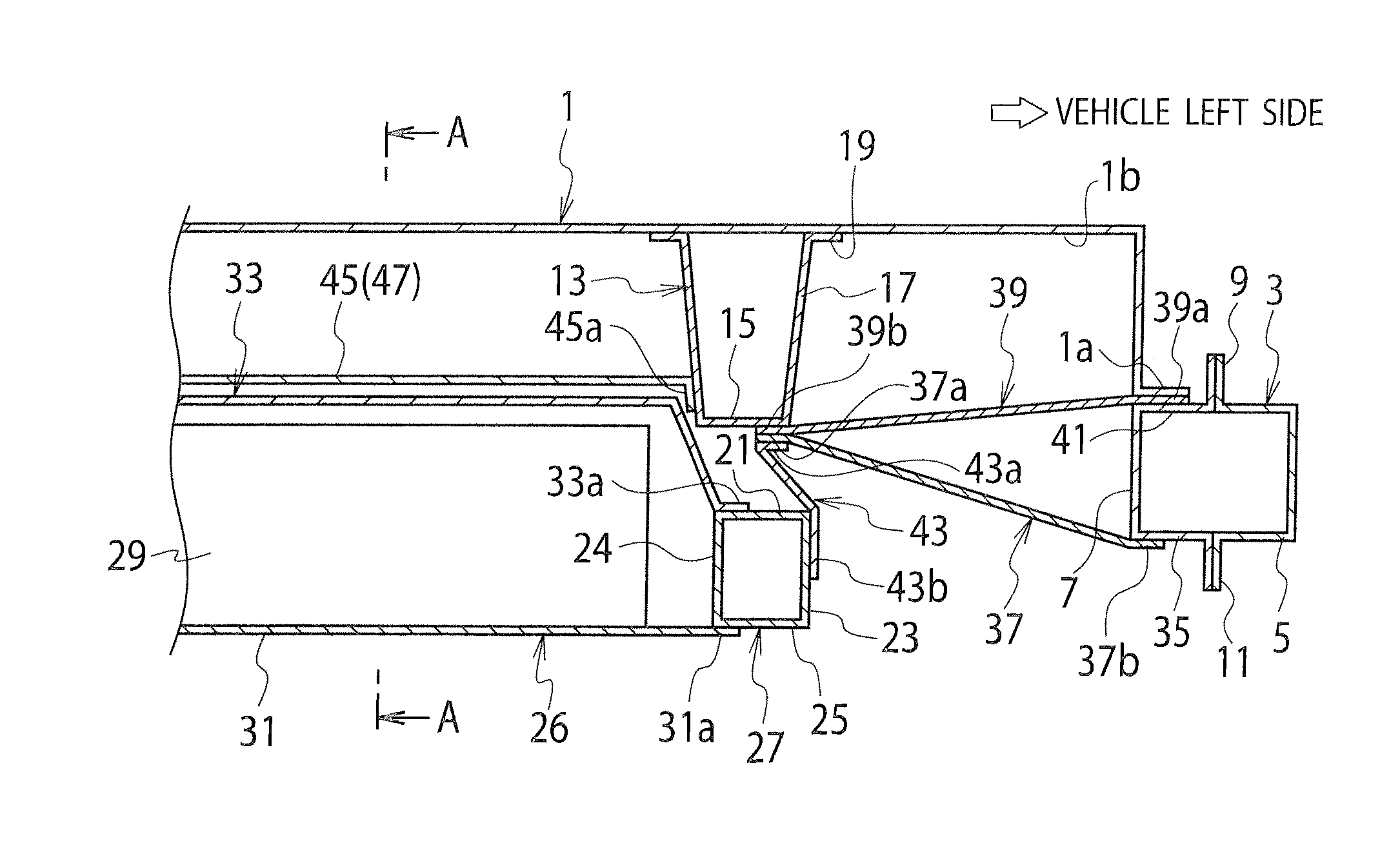
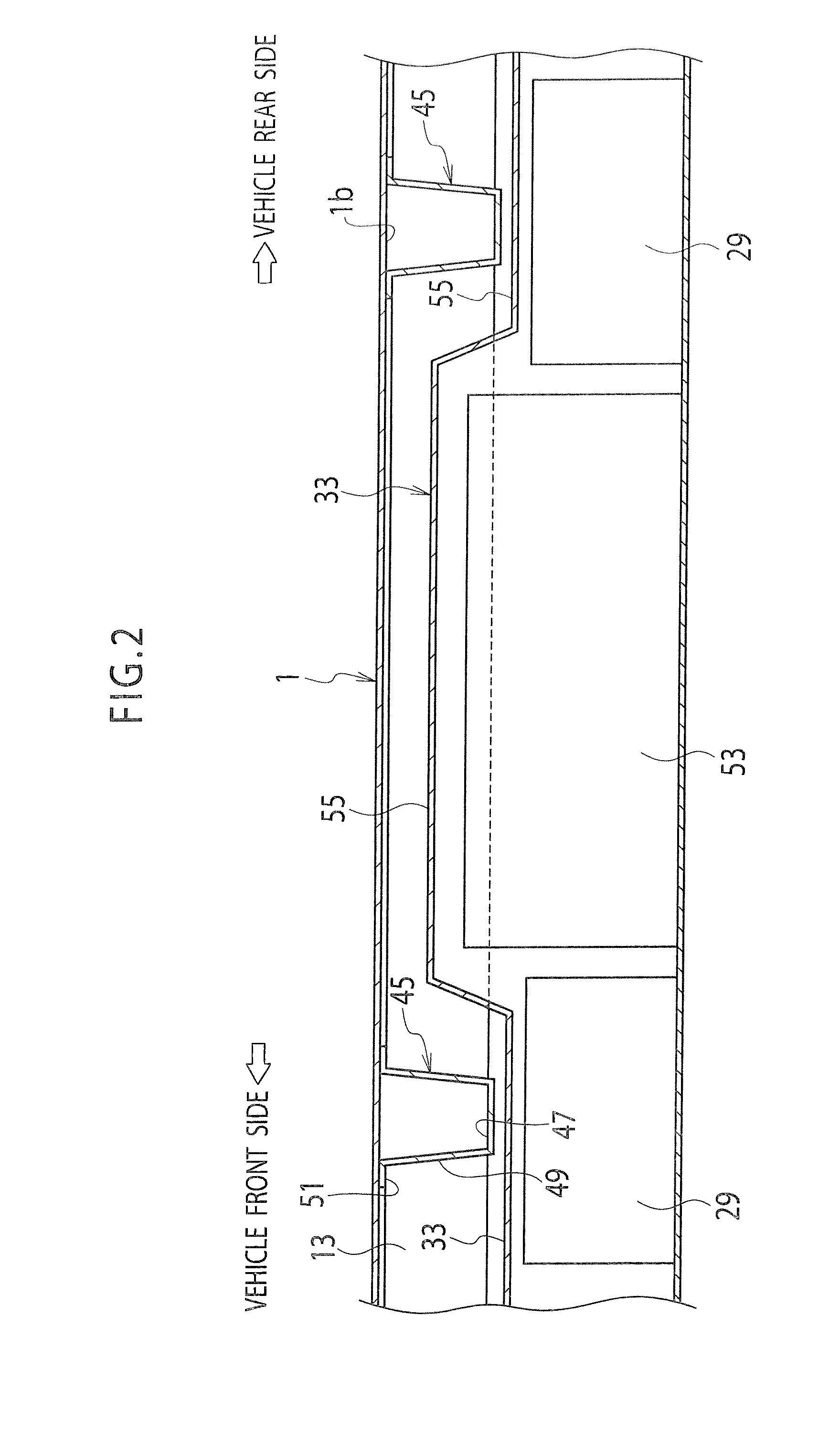
[0013]FIG. 1 to FIG. 3 show an example of a structure for a vehicle body lower portion according to an embodiment of the present invention. This embodiment will be described while taking an electric automobile provided with a so-called stilt floor for example. However, the embodiment is also applicable to a so-called hybrid vehicle and the like besides the electric automobile.

[0014]As shown in FIG. 1, a floor panel 1 of a vehicle body extends substantially horizontally in a vehicle front-rear direction and in a vehicle width direction. A pair of right and left side sills 3, 3 extending in the vehicle front-rear direction are arranged on both sides in the vehicle width direction of the vehicle. Each side sill 3 is formed of a sill outer part 5 and a sill inner part 7 each having a hat-like cross section. To be more precise, the side sill 3 is formed into a rectangular closed ...


PUM


Abstract

A structure for a vehicle body lower portion according to the present invention includes: a side sill (3) located on each side in a vehicle width direction and extending in a vehicle front-rear direction; a side member (13) joined to a lower face (1b) of a floor panel (1) and extending in the vehicle front-rear direction at a position above the side sill (3) and inside the side sill (3) in the vehicle width direction; a brace member (39) connecting a lower part of the side member (13) to an upper side of the side sill (3); and an outer cross member (37) connecting the lower part of the side member (13) to a lower side of the side sill (3).

Description

TECHNICAL FIELD[0001]The present invention relates to a structure for a lower portion of a vehicle body having a battery mounted below a floor.BACKGROUND ART[0002]In an electric vehicle such as an electric automobile, a battery serving as a power source for a motor is normally mounted (see Japanese Patent Application Publication No. Hei 5 (1993)-305879, for example). In the electric automobile described in Japanese Patent Application Publication No. Hei 5-305879, side sills, rear pillars, and rear side members respectively located on both right and left sides of a vehicle body are joined together by using four cross members extending in a vehicle width direction, and a battery is housed and placed in a space surrounded by these cross members.[0003]In addition, each end portion in the vehicle width direction of the cross member located on an upper rear side is connected to an intersection of a lower end portion of the corresponding rear pillar and the corresponding side sill by use o...

Claims


Application Information

Patent Timeline
Patent Type & Authority Applications(United States)
IPC IPC(8): B60R16/04B62D21/00
CPCB62D21/157B62D25/025B62D25/2036B60Y2306/01B62D21/00B60K1/04B60K2001/0438B60R16/04
Inventor MAEDA, TOMOKAZUONODERA, TAKESHI
Owner NISSAN MOTOR CO LTD
Learn More