Apparatus For Providing Electrical Power To Electrical Device And Method Of Use

a technology for electrical devices and apparatuses, applied in the direction of ac network voltage adjustment, sustainable buildings, instruments, etc., can solve the problems of many electrical devices such as hdtvs, printers,

Inactive Publication Date: 2009-06-11
BELKIN INT
View PDF50 Cites 46 Cited by
  • Summary
  • Abstract
  • Description
  • Claims
  • Application Information

AI Technical Summary

Problems solved by technology

Many electrical devices such as televisions, computers, computer monitors, stereo equipment, VCRs (video cassette recorders), DVDs (digital video disk players), printers, scanners, HDTVs (high definition televisions), and the like, can continue to consume power even when switched off.
Over an extended period of time, nominally off electrical devices can consume a significant amount of electrical power and substantially raise the electrical bill of the user.
However, he may forget to turn off the printer, coupled to the computer, and the printer continues to consume electrical power when the person has no intention of using the printer for an extended period of time.

Method used


Image

  • Apparatus For Providing Electrical Power To Electrical Device And Method Of Use
  • Apparatus For Providing Electrical Power To Electrical Device And Method Of Use
  • Apparatus For Providing Electrical Power To Electrical Device And Method Of Use

Examples


first embodiment

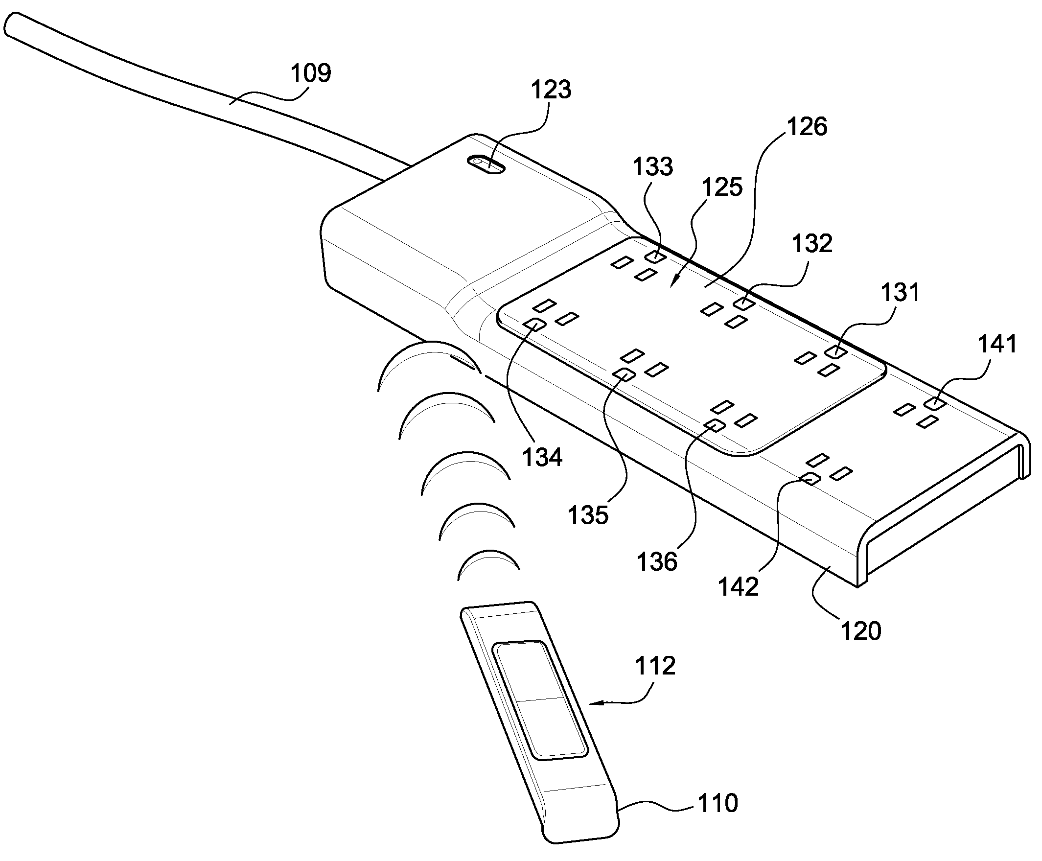
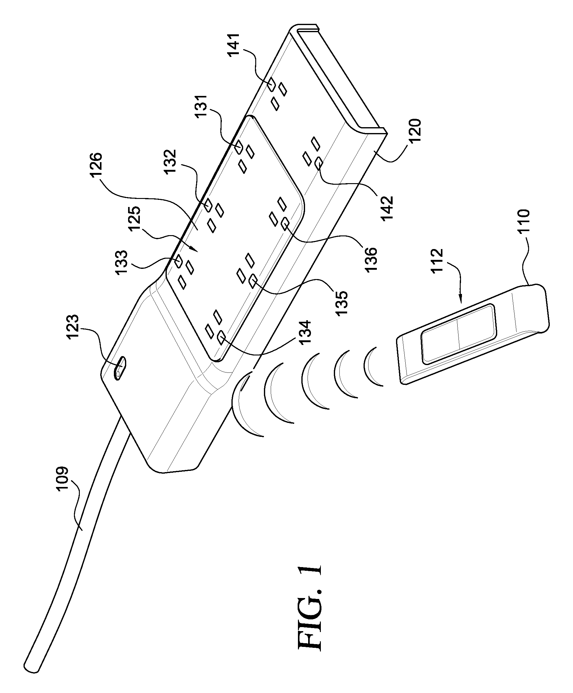
[0037]Turning to the drawings, FIG. 1 illustrates an apparatus 100 for providing power to an electrical device, according to a Apparatus 100 is merely exemplary and is not limited to the embodiments presented herein. Apparatus 100 can be employed in many different embodiments or examples not specifically depicted or described herein.

[0038]In some embodiments, a system or an apparatus 100 for an electrical device (not shown) can include: (a) a control device 110; and (b) an electrical power device 120. Control device 110 can be configured to control electrical power device 120.

[0039]In many examples, a user can input instructions into control device 110, and control device 110 communicates the instructions to electrical power device 120 via a wireless medium. Electrical power device 120 can carry out the instructions from the user and provide electrical power to, or stop providing electrical power to, one or more electrical devices coupled to electrical power device 120. Allowing a ...

second embodiment

[0062]FIG. 4 is a diagram illustrating an electrical power device 420, according to a Electrical power device 420 can be used in apparatus 100 (FIG. 1) in place of or in addition to electrical power device 120 (FIGS. 1 and 2).

[0063]Referring, to FIG. 4, electrical power device 420 can include: (a) one or more electrical outlets 131, 132, and 133; (b) two or more switches 425, 426, and 427 electrically coupled to electrical outlets 131, 132, and 133, respectively; (c) a receiver 422 electrically coupled to switches 425, 426, 427; (d) power toggle mechanism 123 electrically coupled to electrical outlets 131, 132, and 133 (e) plug 211 electrically coupled to power toggle mechanism 123, switches 425, 426, 427, electrical outlets 131, 132, and 133, and receiver 422, and (f) cable 109 coupling plug 211 to power toggle mechanism 123, switches 425, 426, 427, and electrical outlets 131, 132, and 133.

[0064]In the embodiment illustrated in FIG. 4, receiver 422 receives user instructions via a...

third embodiment

[0066]FIG. 5 is a diagram illustrating an electrical power device 520, according to a Electrical power device 520 can be used in apparatus 100 (FIG. 1) in place of or in addition to electrical power device 120 (FIGS. 1 and 2) and / or electrical power device 420 (FIG. 4).

[0067]Referring to FIG. 5, electrical power device 520 can include: (a) one or more electrical outlets 131, 132, 133, and 134; (b) one or more switches 581, 582, 583, and 584; (c) one or more receivers 571, 572, 573, and 574; (c) electrical plug 211 electrically coupled to electrical outlets 131, 132, 133, 134, switches 581, 582, 583, and 584, and receivers 571, 572, 573, and 574; and (d) cable 109 coupling electrical plug 211 to electrical outlets 131, 132, 133, and 134 and switches 581, 582, 583, and 584.

[0068]In the embodiment illustrated in FIG. 5, each of electrical outlets 131, 132, 133, and 134 are coupled to an individual switch, and the switch is coupled to a separate receiver. That is, electrical outlets 13...


PUM


Abstract

In some embodiments, a surge protector includes: (a) an electrical connector configured to receive electrical power; (b) one or more receivers configured to receive input via wireless signals; (c) at least one first switch electrically coupled to the electrical connector; (d) one or more first electrical outlets; and (e) one or more second electrical outlets electrically coupled to the electrical connector. In these embodiments, each switch of the at least one first switch is electrically coupled to at least one of the one or more first electrical outlets and at least one of the one or more receivers. The at least one first switch is configured to turn on or turn off the electrical power to the one or more first electrical outlets based on the input received by the one or more receivers. Furthermore, the one or more second electrical outlets are coupled to the electrical connector such that when the electrical connector receives electrical power, the one or more second electrical outlets receive electrical power. Other embodiments are disclosed in this application.

Description

CROSS-REFERENCE TO RELATED APPLICATIONS[0001]This application claims the benefit of U.S. Provisional Application No. 60 / 977,312, filed Oct. 3, 2007 and U.S. Provisional Application No. 60 / 977,248, filed Oct. 3, 2007.[0002]This is also a continuation-in-part application of U.S. application Ser. No. 12 / 034,836, filed Feb. 21, 2008. U.S. Provisional Application Nos. 60 / 977,312 and 60 / 977,248 and U.S. application Ser. No. 12 / 034,836 are incorporated herein by reference.DESCRIPTION OF THE BACKGROUND[0003]Many electrical devices such as televisions, computers, computer monitors, stereo equipment, VCRs (video cassette recorders), DVDs (digital video disk players), printers, scanners, HDTVs (high definition televisions), and the like, can continue to consume power even when switched off. Over an extended period of time, nominally off electrical devices can consume a significant amount of electrical power and substantially raise the electrical bill of the user. One study found that 23% of el...

Claims


Application Information

Patent Timeline
Patent Type & Authority Applications(United States)
IPC IPC(8): H02J3/00
CPCG06F1/266G06F2200/261Y04S20/16Y02B90/226H02J13/0065H02J13/00019H02J13/0005Y02B90/20Y04S20/00
Inventor MORI, KENNETHIIDA, YOKOROEPKE, JONGANDHI, HANOZHERMAN, GID
Owner BELKIN INT
Why Eureka
Try Eureka