Touch sensing display device and driving method thereof

Inactive Publication Date: 2009-06-11
SAMSUNG DISPLAY CO LTD
View PDF3 Cites 31 Cited by
  • Summary
  • Abstract
  • Description
  • Claims
  • Application Information

AI Technical Summary

Benefits of technology

[0039]Also, the positions of all touch regions generated during one sensor frame can be determined during sequential processing of the sensing

Problems solved by technology

Such sensing element also increases the difficulty in displaying minute characters or pictures.
However, when several positions are simultaneously touch

Method used


Image

  • Touch sensing display device and driving method thereof
  • Touch sensing display device and driving method thereof
  • Touch sensing display device and driving method thereof

Examples


Embodiment Construction

[0053]In the following detailed description, only certain exemplary embodiments of the present invention are shown and described as an illustration of the present invention.

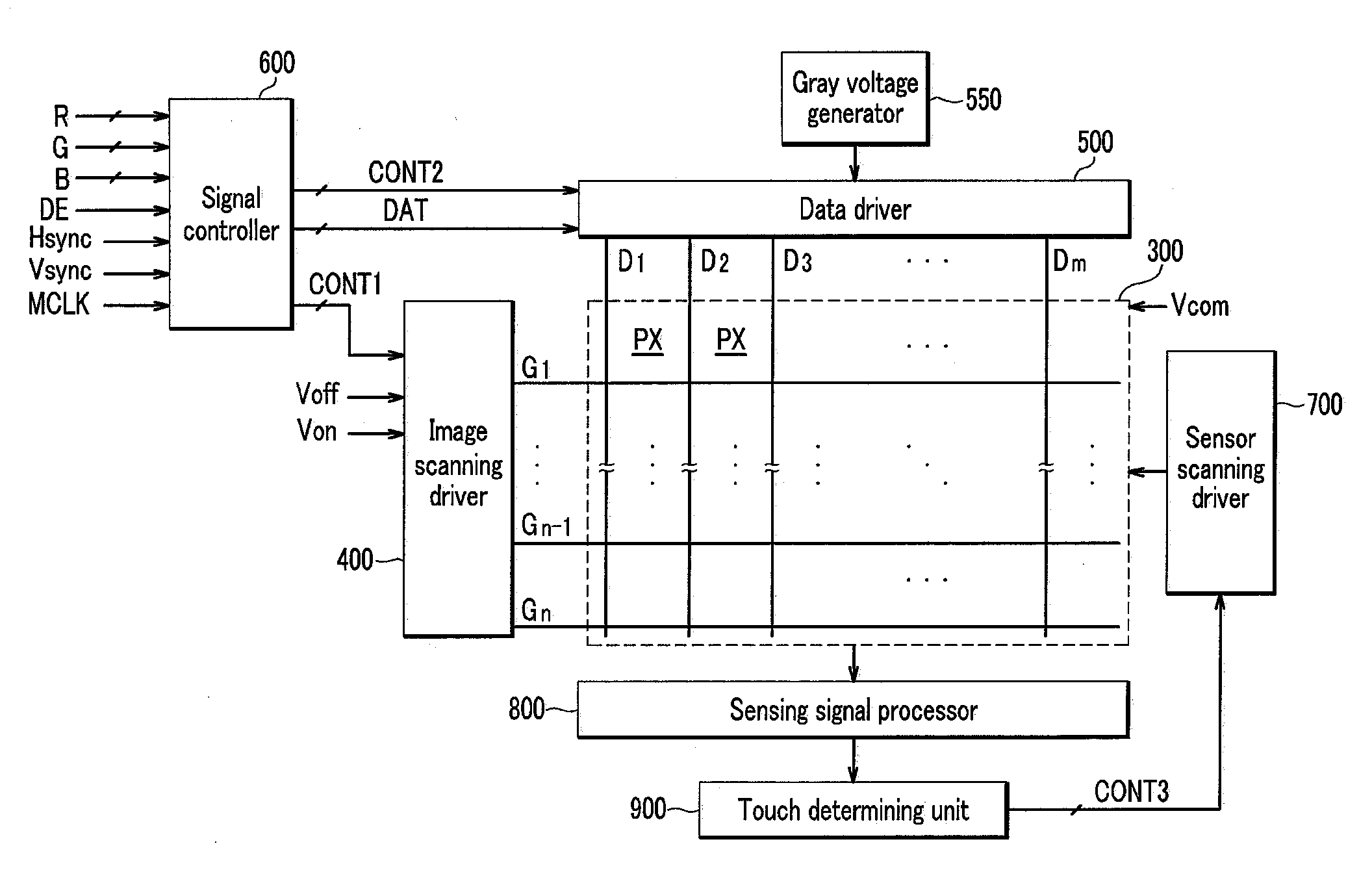
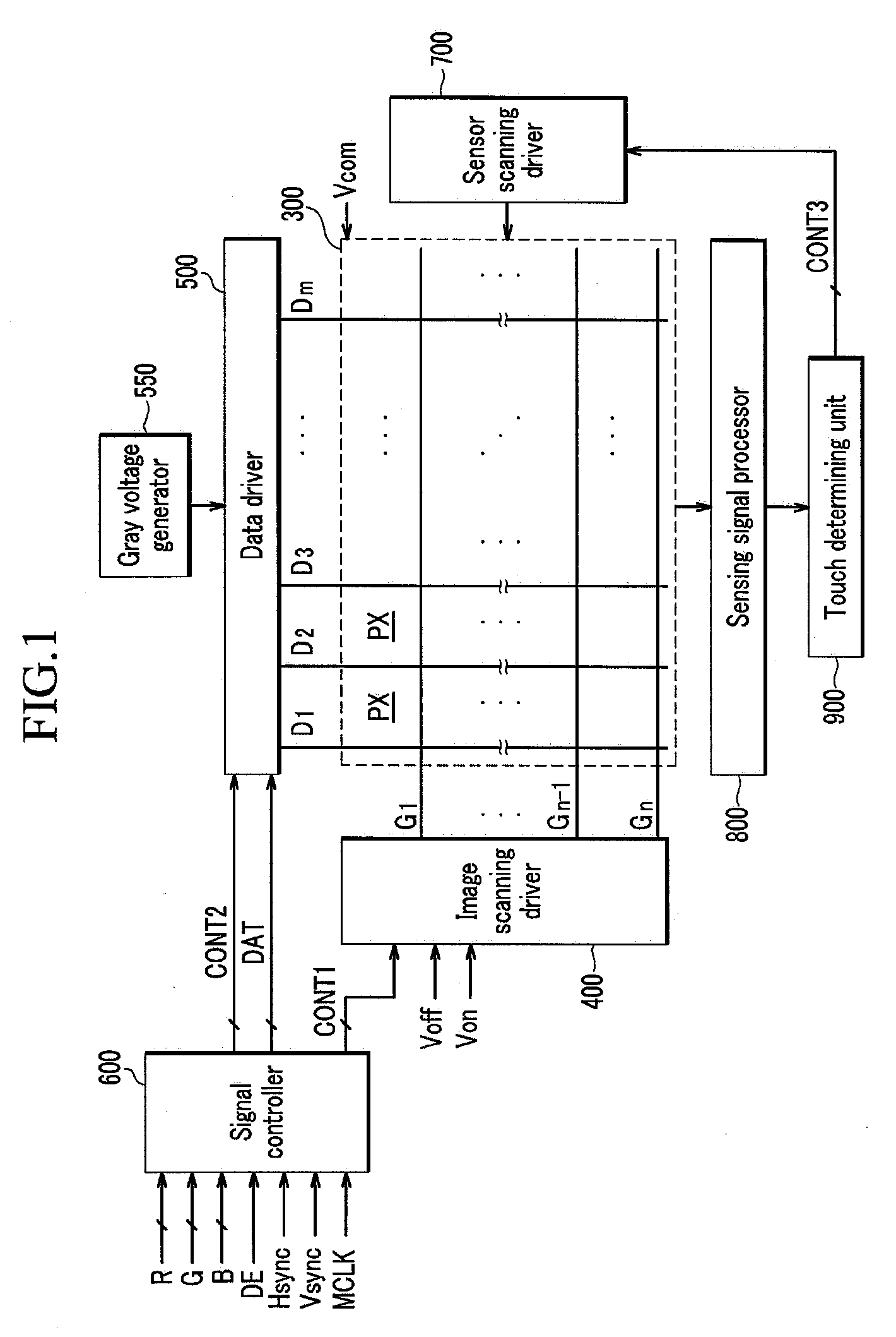
[0054]Firstly, a touch sensing display device according to an exemplary embodiment of the present invention is described in detail with the reference to FIG. 1 to FIG. 6. Specifically, a liquid crystal display is described as one example of the display device according to an exemplary embodiment of the present invention.

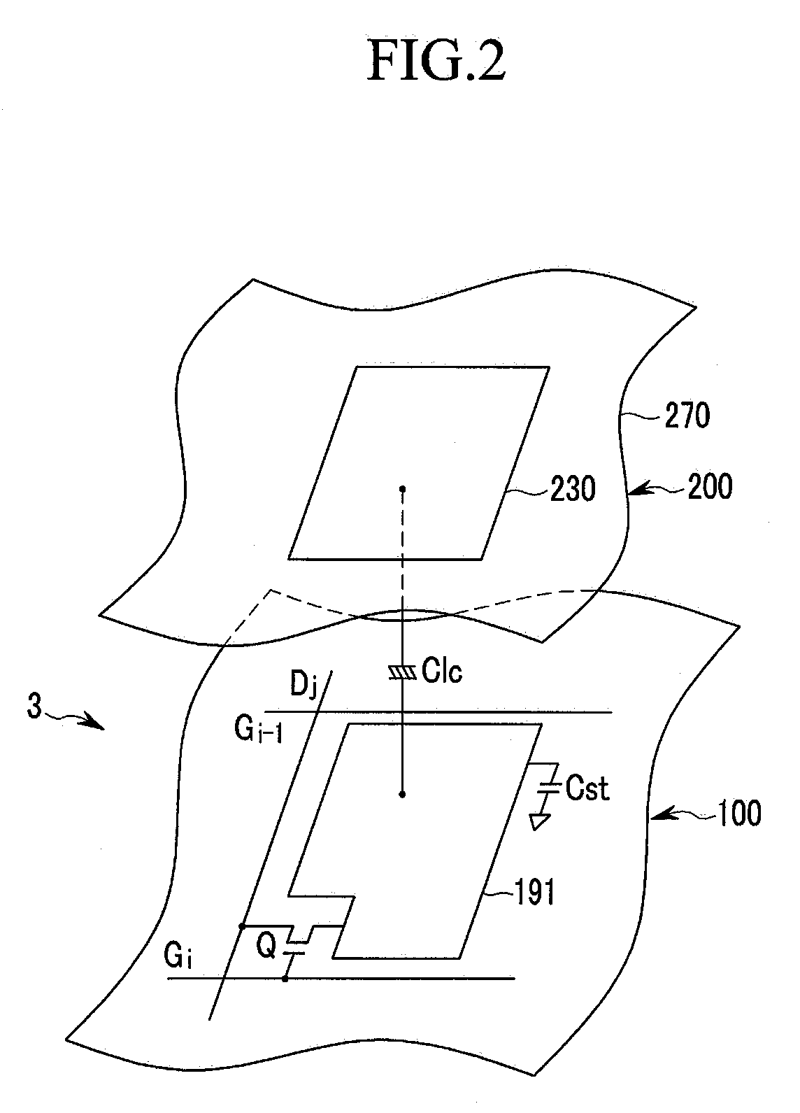
[0055]FIG. 1 is a block diagram of a liquid crystal display according to an exemplary embodiment of the present invention, FIG. 2 is an equivalent circuit diagram of one pixel in the liquid crystal display according to an exemplary embodiment of the present invention, FIG. 3 is a block diagram of a portion of the liquid crystal display according to an exemplary embodiment of the present invention, FIG. 4 is an equivalent circuit diagram of a sensing element in the liquid crystal display according ...


PUM


Abstract

In a touch sensing display device, a plurality of sensor scanning lines extend in a first direction and sequentially receive a first voltage, and a plurality of sensor data lines extend in a second, different, direction. A plurality of sensing elements are formed in regions defined by the sensor scanning lines and the sensor data lines, and each sensing element transmits the first voltage from a corresponding sensor scanning line to a corresponding sensor data line responsive to an external touch. A sensing signal processor converts voltages of the sensor data lines into sensing data, and, a touch determining unit processes the sensing data corresponding to the sensor scanning lines by at least one scanning line to determine positions of touch regions generated during at least one frame.

Description

CROSS-REFERENCE TO RELATED APPLICATION[0001]This application claims priority to and the benefit of Korean Patent Application No. 10-2007-0127679 filed in the Korean Intellectual Property Office on Dec. 10, 2007, the entire contents of which are incorporated herein by reference.BACKGROUND OF THE INVENTION[0002](a) Field of the Invention[0003]The present invention relates to a display device and a driving method thereof. More particularly, the present invention relates to a touch sensing display device and a driving method thereof.[0004](b) Description of the Related Art[0005]Generally, display devices include a plurality of pixels arranged in a matrix, and images are displayed by controlling the light intensities of each pixel according to given luminance information. A liquid crystal display device in particular, includes a pixel electrodes display panel, a common electrode display panel, and a liquid crystal layer with dielectric anisotropy positioned between the two display panels...

Claims


Application Information

Patent Timeline
IPC IPC(8): G06F3/041G09G5/00
CPCG06F3/0416G06F3/0412G06F3/04166G06F3/047G02F1/1335G02F1/133
Inventor PARK, JONG-WOUNGMA, WON-SEOKKIM, HYUNG-GUELLEE, SUNG-WOOLEE, JOO-HYUNGJEON, BYUNG-KIUH, KEE-HAN
Owner SAMSUNG DISPLAY CO LTD
Why Eureka
Try Eureka