Wireless remote passive temperature sensor for monitoring food

a passive temperature sensor and wireless technology, applied in the field of wireless temperature sensors, can solve the problems of inconvenient installation and removal, wireless temperature sensors that require semiconductor components to operate, and systems that have not been successfully developed, and achieve the effect of increasing inductan

Inactive Publication Date: 2009-06-11
WT SYST
View PDF1 Cites 27 Cited by
  • Summary
  • Abstract
  • Description
  • Claims
  • Application Information

AI Technical Summary

Benefits of technology

The present invention is about using a loop antenna to transmit a swept sinusoidal signal to a remote wireless temperature sensor that is inserted in food. The sensor has a coil of wire and a small amount of material like mercury or Galinstan, which causes an increase in inductance and a decrease in resonant frequency as temperature increases. This change in resonant frequency is proportional to temperature. The loop antenna is located remotely from the sensor and is able to operate at elevated temperatures for prolonged periods without requiring semiconductor components.

Problems solved by technology

The patent text describes a problem with traditional food temperature monitoring systems that use wired probes and readers. These systems limit the movement of the food and are inconvenient to install and remove. The text also mentions the difficulty in developing wireless temperature sensors that can operate at elevated temperatures, such as when cooking food. The technical problem addressed by this patent is the need for a wireless temperature sensor that is cost-effective and can be used for multiple food objects.

Method used


Image

  • Wireless remote passive temperature sensor for monitoring food
  • Wireless remote passive temperature sensor for monitoring food
  • Wireless remote passive temperature sensor for monitoring food

Examples


Embodiment Construction

[0016]The present wireless temperature sensor has been developed principally for use while cooking to permit remote monitoring of food temperature.

[0017]Consequently the description of the invention will be specifically with reference to such a food monitoring application although it will be readily apparent that many other uses are possible.

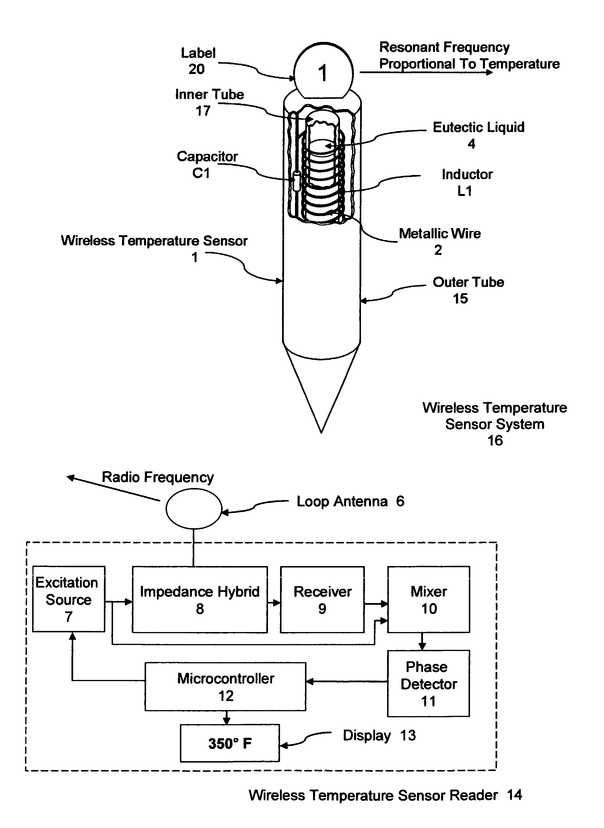
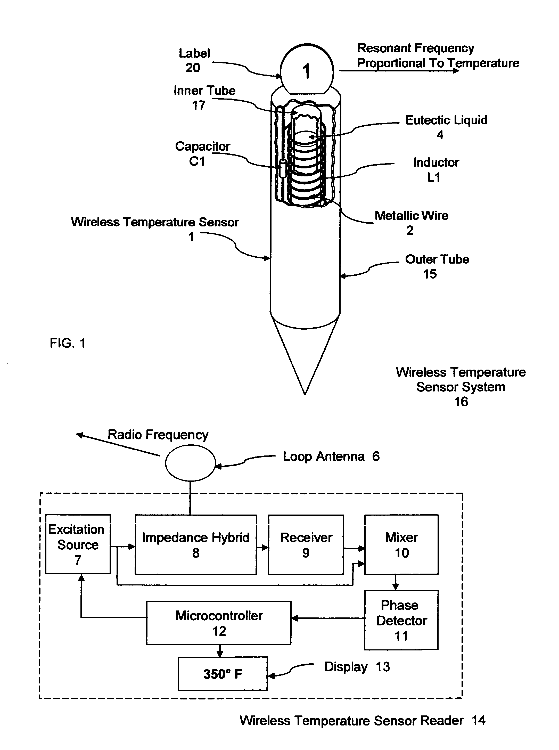
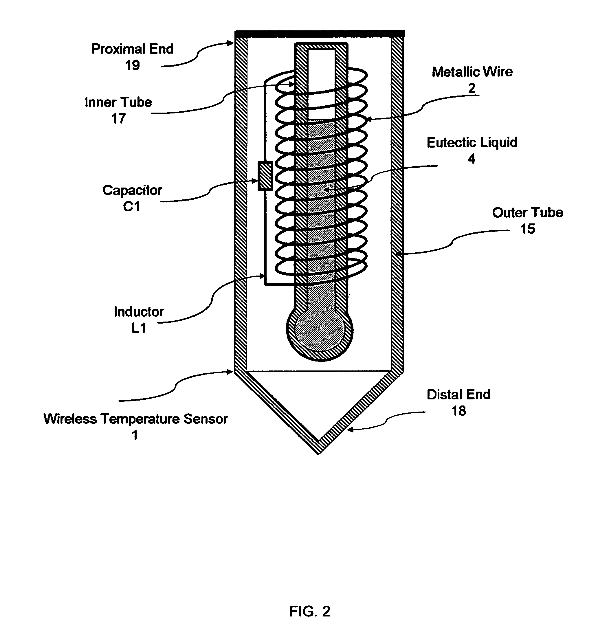
[0018]FIG. 1, shows a wireless temperature sensor system 16, in accordance with certain preferred embodiments of the present invention. A wireless temperature sensor 1, as shown, is preferably inserted into the food being cooked for continuously monitoring the internal temperature of the food. The wireless temperature sensor 1, comprises metallic wire 2, wrapped around a non-metallic inner tube 17, capable of withstanding repeated exposure to 500° F. for extended periods of time. The coiled wire 2, wrapped around the inner tube 17, creates an air core inductor L1. The ends of the wire 2, are connected to capacitor C1, to create an LC “tank” circ...


PUM


Abstract

A passive wireless temperature sensor with a loop antenna is placed in a remote environment for exposure to its changing temperature conditions. The sensor includes a coil of wire wrapped around a cylinder to form an air-core inductor. The cylinder contains a small amount of eutectic material similar to a conventional thermometer which has the property of being magnetic. A capacitor is connected to the coil of wire to form a resonant LC “tank” circuit. As temperature increases, the eutectic material expands through the cylinder at the core of the inductor causing an increase in inductance and corresponding decrease in the resonant frequency of the LC “tank” circuit. The temperature of the remote sensor is proportional to resonant frequency and can be determined by generating an oscillating signal and measuring resonant frequency of the remote sensor.

Description


Claims


Application Information

Patent Timeline
Owner WT SYST
Why Eureka
Try Eureka