
Mutual inductance in transformer based tank circuitry

a transformer and transformer technology, applied in the direction of pulse generator, pulse technique, electrial characteristics varying frequency control, etc., can solve problems such as circuit losses, reduce the value of parasitic resistance, minimize energy loss, and reduce the resistance of the sheet

Active Publication Date: 2007-07-31
INTELLECTUAL VENTURES HOLDING 81 LLC
View PDF15 Cites 49 Cited by
  • Summary
  • Abstract
  • Description
  • Claims
  • Application Information

AI Technical Summary

Benefits of technology

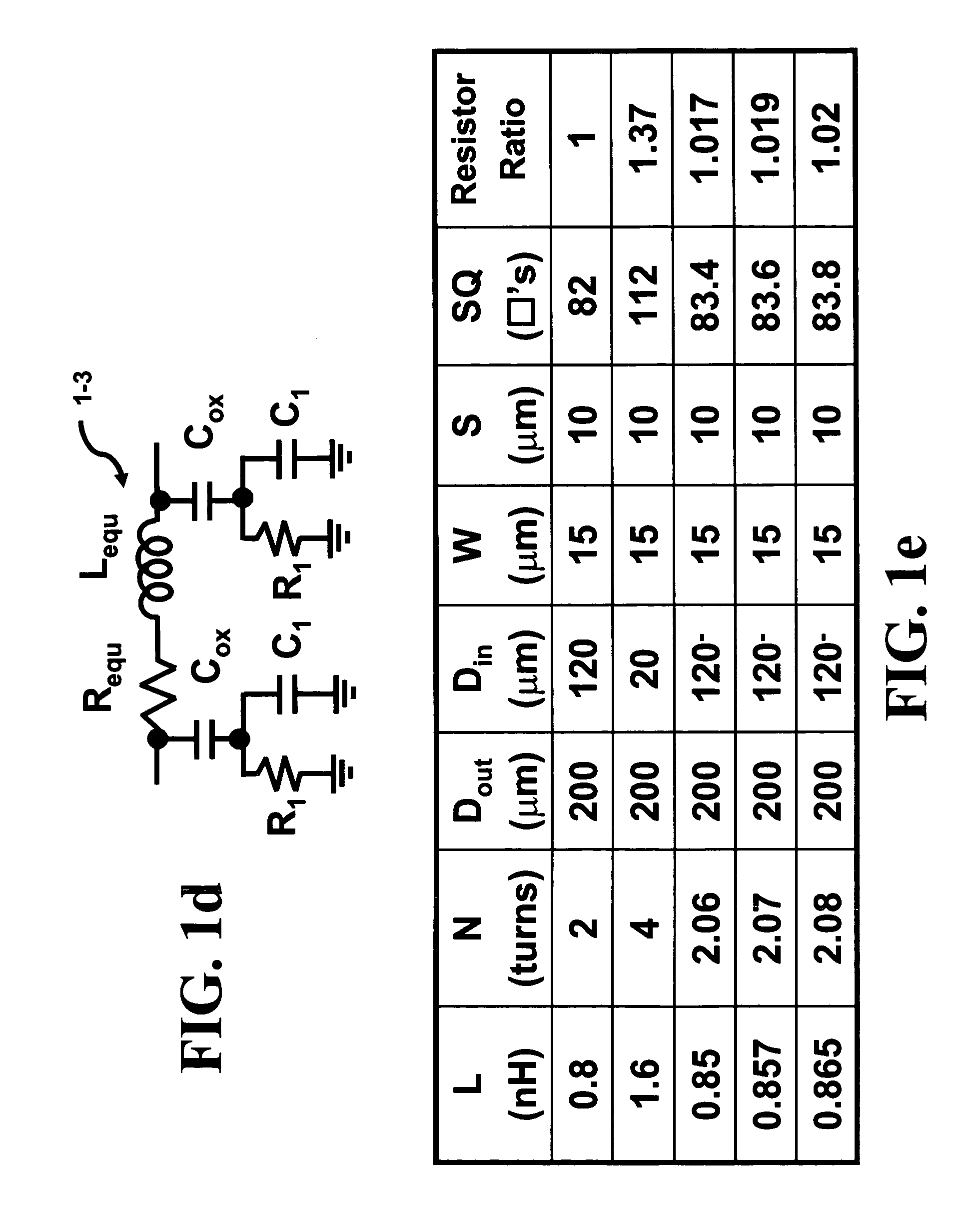
[0015]Inductors are used in a variety of circuits. In the manufacture of the inductor, there is a parasitic resistive element contained within the inductor. This parasitic element causes losses in the circuit. The goal is to reduce the value of this parasitic resistance as much as possible in order to minimize the energy loss as indicated by the previous references. This procedure effectively lowers the sheet resistance since the overall metal sheet resistance decreases. However, it would be desirable to decrease the parasitic resistance, decrease the flow of eddy current within the metallic conductor of the inductor, and adjust the mutual coupling between two parallel-connected inductors thereby controlling the value of the overall effective inductance.
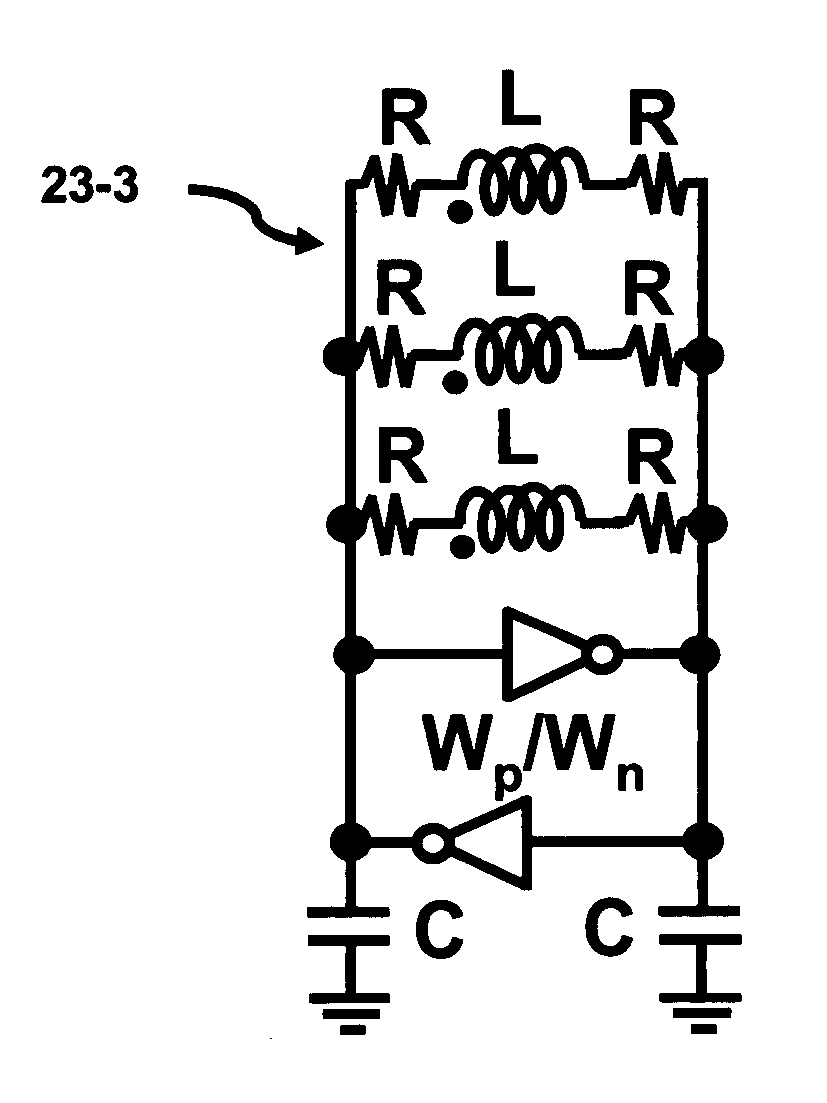
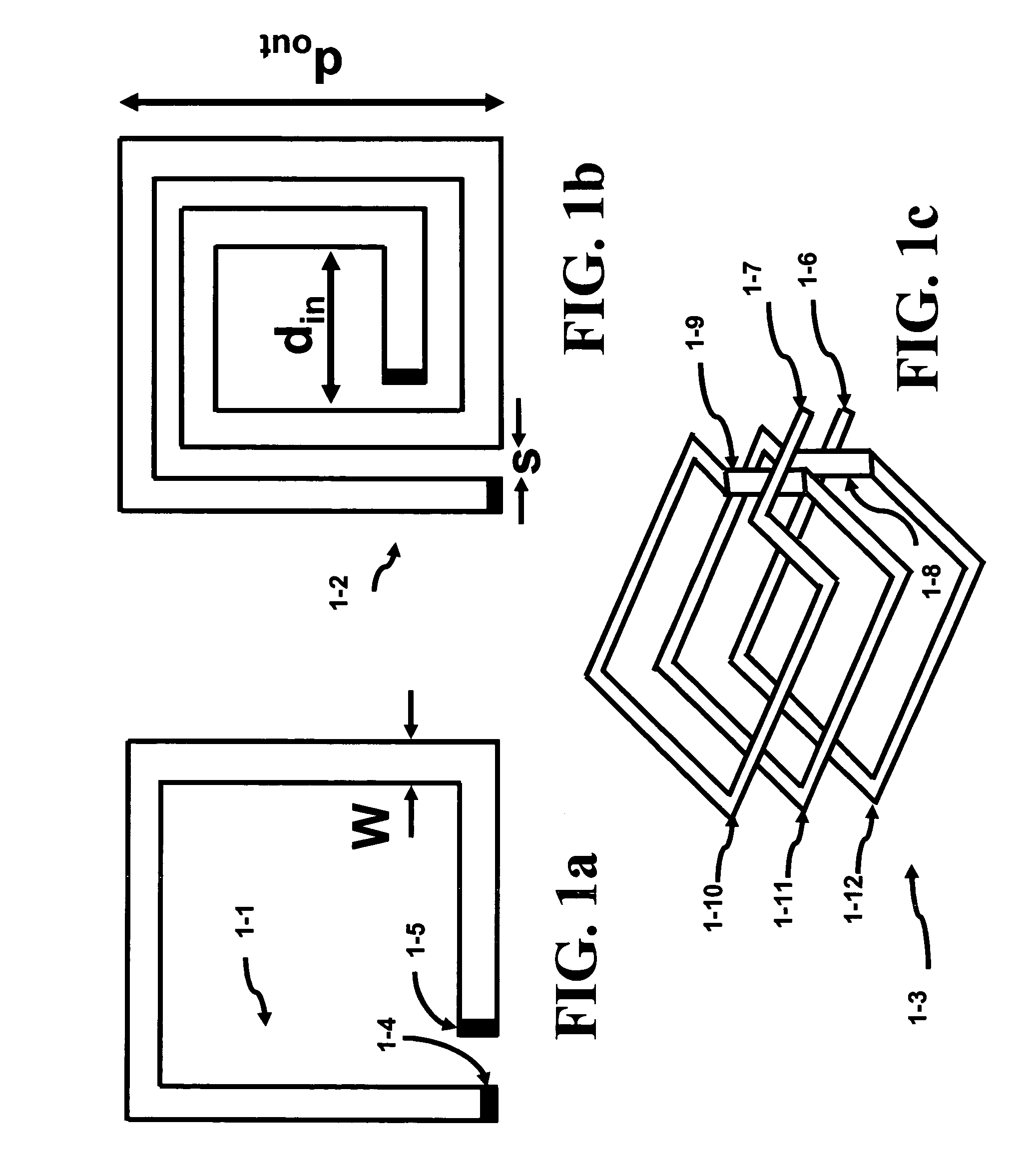
[0017]Another aspect of this invention is to reduce the parasitic resistance of a parallel combination of inductors, yet prevent the full effect of the parallel reduction rule to reduce the overall inductance value. The key aspect of this invention is to utilize the magnetic coupling between the two inductors to compensate for this inductance reduction. The structure to obtain this behavior is known as the transformer. In order for this idea to function, the transformer is connected in a particular configuration that allows the reduction of the parasitic resistance but attempts to maintain the value of the inductance at its original value. In its simplest form, the transformer consists of two identical inductors that have a mutual coupling coefficient k. This value can be adjusted within the range of 0 to that approaching 1. Lenz's law is utilized to increase the overall inductance by using the magnetic coupling between the two coils to effectively increase the inductance of coils that are mutually coupled together. Thus, when two identical inductors in the transformer are connected in parallel and the mutual coupling coefficient k is close to 1, the parasitic resistance decreases in half, but the final inductance value is nearly equal to the initial inductance value of either inductor. A further benefit of this technique in a planar technology is that an inductor can be segmented into parallel strips along its length according to this invention and thereby reducing the eddy current loss within the inductor. By maintaining the coefficient k large between these parallel strips, the initial value of the inductor can be maintained while simultaneously achieving a decrease in eddy current loss.

Problems solved by technology

This parasitic element causes losses in the circuit.

Method used


Image

  • Mutual inductance in transformer based tank circuitry
  • Mutual inductance in transformer based tank circuitry
  • Mutual inductance in transformer based tank circuitry

Examples


Embodiment Construction

[0071]The LC (inductor-capacitor) tank circuit has been a fundamental building block in many electrical system designs. This circuit is used in the wireless, digital, and mixed-signal designs. The basic building elements of the LC tank circuit consist of an inductor and capacitor.

[0072]The invention is based on the discovery that a transformer can be used to decrease the effective resistance of an equivalent inductance that is applied to a capacitive load while maintaining a higher inductance value. The coupling coefficient of the transformer can be utilized to increase the effective inductance presented to the capacitor yet significantly reduce the resistance of the equivalent inductance of the transformer. The ability to reduce the resistance will offer an improvement in the Q or quality factor of the inductor.

[0073]In addition, this technique offers a degree of freedom in the design of tank circuits, which did not exist previously. For example, tradeoffs between single and multi-...


PUM


Abstract

Placing inductors or resistors in parallel causes the combined value of inductance or resistance to decrease according to the parallel combination rule. This invention decreases the parasitic resistance of an inductor by placing several inductors in parallel. Furthermore, by careful placement of these inductors, the mutual inductance between these inductors can be used to increase the equivalent inductance value to a value near that of the original inductance value of a single inductor. Thus, it is possible to create an inductance with a much lower value of parasitic resistance. This invention allows the formation of high Q inductors and would be beneficial in any circuit design requiring inductances. Another aspect of this invention is that the coils can be partitioned to minimize eddy current losses. This invention can easily be implemented in a planar technology. Simulations of several tank circuits indicate that the power dissipation can be reduced 3 to 4 times when compared to conventional techniques.

Description

CROSS-REFERENCE TO RELATED APPLICATIONS[0001]The present application is related to the co-filed U.S. applications Ser. Nos. 11 / 184,767, 11 / 185,001, and 11 / 184,428 filed on Jul. 19, 2005, which are invented by the same inventor as the present application and incorporated herein by reference in their entireties.BACKGROUND OF THE INVENTION[0002]Electronic consumer products are pushing both the bounds of portability and computation complexity, in certain cases, simultaneously. Today mobility implies that the product has attributes such as the capability of being wireless. In addition, since video is playing a larger role in our lives every day, the need for low power computation techniques and high performance for video applications for both mobile and desktop systems is required.[0003]An oscillator block provides the ability to regulate the flow of computation data within a VLSI (Very Large Scale Integration). For instance, the on chip clock frequency of a high-end microprocessor is ex...

Claims


Application Information

Patent Timeline
Patent Type & Authority Patents(United States)
IPC IPC(8): H03B5/12
CPCH03B5/1841H03B5/1215H03B5/1221H03B5/124H03B5/1228H03B5/1212
Inventor GABARA, THADDEUS JOHN
Owner INTELLECTUAL VENTURES HOLDING 81 LLC
Learn More