
Wireless charging system, battery with wireless charging function and electronic devices with the same

a wireless charging and wireless charging technology, applied in secondary cell servicing/maintenance, electrochemical generators, safety/protection circuits, etc., can solve the problems of increasing the concerns of conventional battery chargers, the cords of conventional corded battery chargers are unsightly and have a tendency to become tangled, etc., to enhance the charging efficiency, advance the dependability, and facilitate the wireless charging method

Inactive Publication Date: 2012-04-26
SAE MAGNETICS (HK) LTD
View PDF2 Cites 46 Cited by
  • Summary
  • Abstract
  • Description
  • Claims
  • Application Information

AI Technical Summary

Benefits of technology

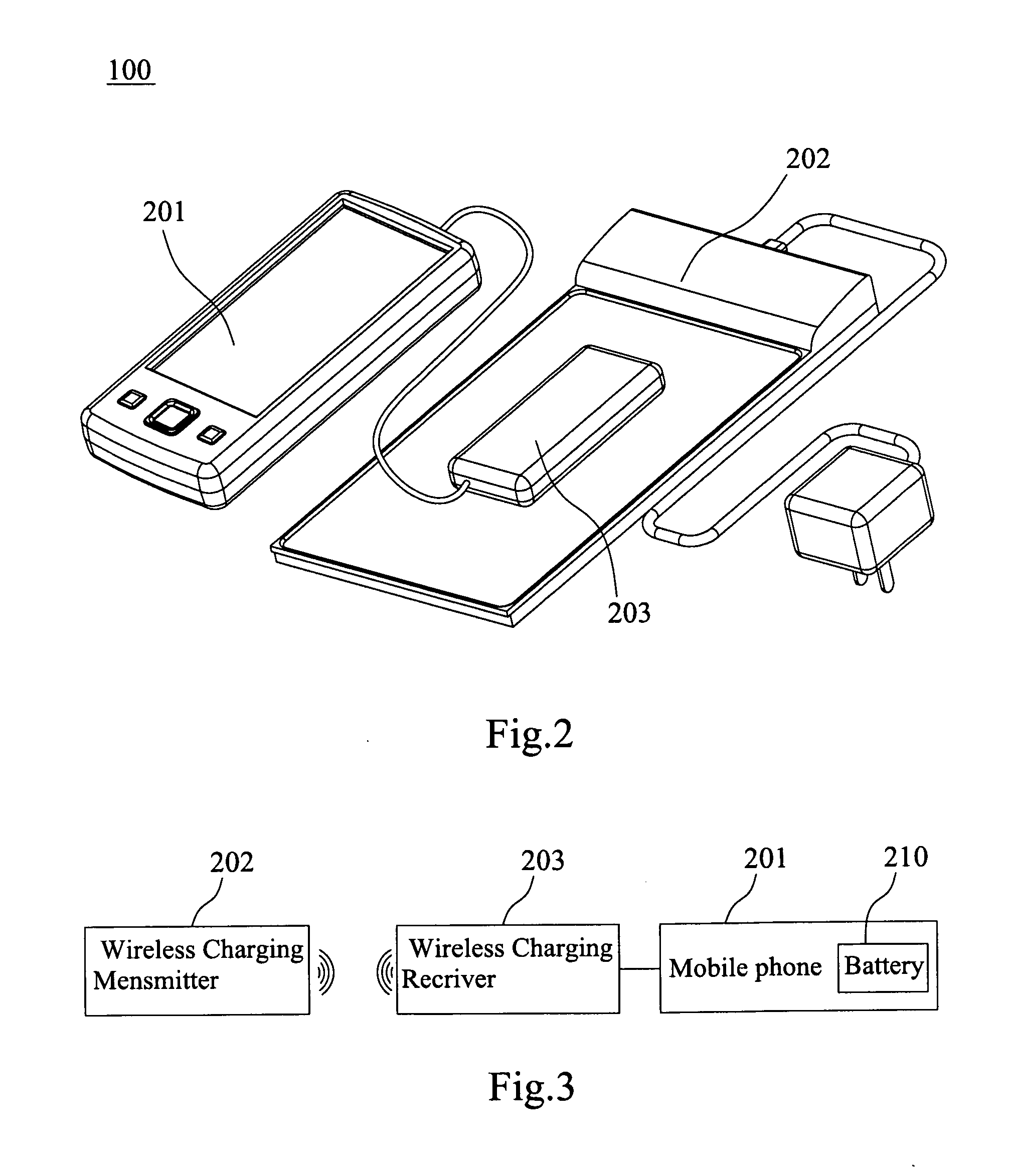
The present invention provides a new battery as a receiver adapted to a wireless charging system with a wireless transmitter. The battery has a coil, a PCB, a core, a shield, and a case. The coil is connected to the PCB to induce the magnetic power transmitted from the transmitter and generate inductive current. The PCB is integrated with a resonant circuit, a rectifying circuit, a charging circuit, and a battery protect circuit to transform the inductive current into electrical power and protect the battery from overcharge and short. The battery can be charged by any kind of wireless transmitter without an extra receiver. The technical effect of this invention is to provide a wireless charging system with a new battery that can be charged by any kind of wireless transmitter without an extra receiver.

Problems solved by technology

With continued growth in the use of battery-operated portable electronic devices, there are increasing concerns about the problems associated with conventional battery chargers.
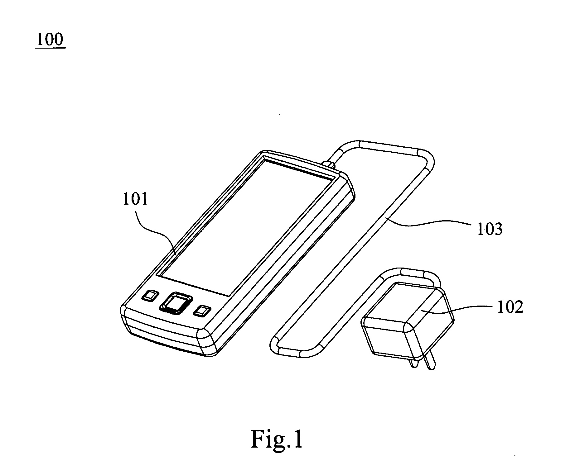
The design of the corded battery charger 100, usually including power specifications and plug configuration, typically varies from device to device such that a battery charger of one device is not likely to operate properly in charging the batteries of another device.
In addition, the cords of conventional corded battery chargers are unsightly and have a tendency to become tangled both alone and with cords of other chargers.
What's more, corded chargers are also relatively inconvenient because a user is required to plug and unplug the cord each time the device is charged, and huge standby power of adapter is a big waste for energy saving.
Although the conventional wireless charging system can be a marked improvement over wired chargers, they continue to suffer from some inconveniences.
Thus, the user cannot operate the wireless electronic device in a wireless manner so that the convenience in using the conventional wireless chargers is low.

Method used


Image

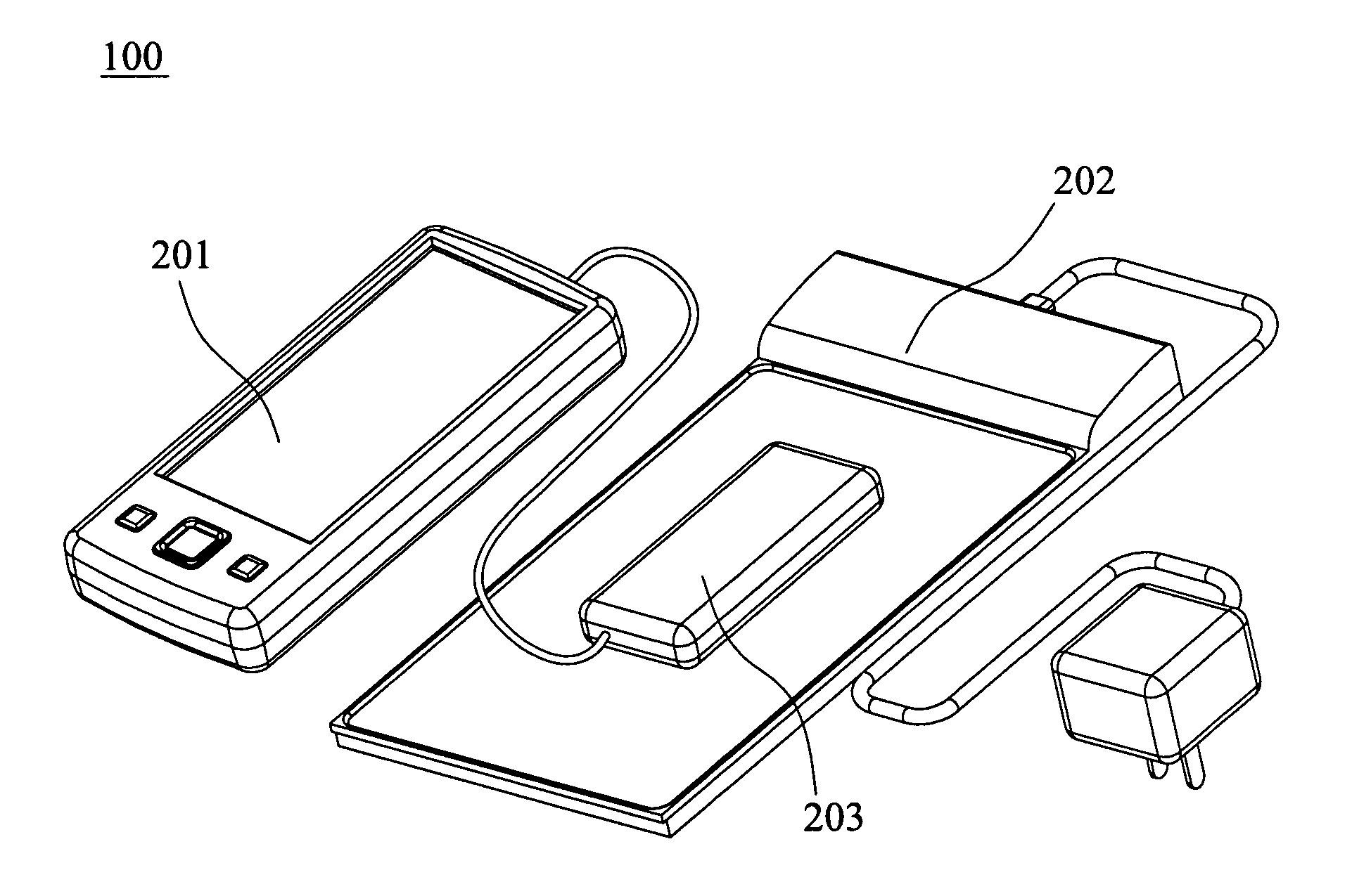
  • Wireless charging system, battery with wireless charging function and electronic devices with the same
  • Wireless charging system, battery with wireless charging function and electronic devices with the same
  • Wireless charging system, battery with wireless charging function and electronic devices with the same

Examples


first embodiment

[0061]Referring to FIG. 7, FIG. 7 is a perspective view of a wireless charging system 300 according to the present invention. The wireless charging system 300 includes a transmitter 310 and a electronic device 320 as a receiver to realize wireless charging function, thereof the transmitter 310 is used to generate magnetic power and transmit it, and the electronic device 320 is used to induce the magnetic power transmitted from the transmitter 310 and store electric power transformed from the magnetic power. The electronic device 320 can be charged by near or on the transmitter 310, so it doesn't need to be electrically connected to an extra receiver to realize wireless charging function.

[0062]Referring to FIG. 8 and FIG. 9, FIG. 8 is a block diagram showing the transmitter of a wireless charging system according to the first embodiment of the present invention, and FIG. 9 is a detailed circuit of the block diagram of the transmitter shown in FIG. 8. As illustrated, the transmitter 3...

second embodiment

[0067]Now referring to FIG. 19, FIG. 19 illustrates an electronic device 520 adapted to a wireless charging system according to the present invention. The electronic device 520 comprises a housing (not shown) with a main frame and a back cover 542, a coil 543, a shield 544 and a battery 550. The battery 550 is configured to be housed in the housing, that is, the battery 550 is attached to the main frame of the housing, and the back cover 542 of the housing is configured to cover the coil 543, the shield 544 and the battery 550. The coil 543 is configured to induce the magnetic power transmitted from the transmitter of the wireless charging system to generate inductive current for the battery 550. The coil 543 can be printed on the back cover 542 of the housing by plating, etching or silkscreen process. Alternatively, or in addition, the coil 543 could be an independent coil which is over-molded into the back cover 542 of the housing. The shield 544 is sandwiched between the coil 543...

third embodiment

[0068]FIG. 21 illustrates an electronic device 620 adapted to a wireless charging system according to the present invention. The electronic device 620 comprises a housing (not shown) with a main frame and a back cover 642, a coil 643, a shield 644, a PCB 645 and a battery 650. The battery 650 is configured to be attached to the main frame of the housing, and the back cover 642 of the housing is configured to cover the coil 643, the shield 644, the PCB 645 and the battery 650. The coil 643 is configured to induce the magnetic power transmitted from the transmitter of the wireless charging system to generate inductive current for the battery 650. The coil 643 can be printed on the back cover 642 of the housing by plating, etching or silkscreen process. Alternatively, or in addition, the coil 643 could be an independent coil which is over-molded into the back cover 642 of the housing. The shield 644 is sandwiched between the coil 643 and the battery 650 to protect the battery 650 from ...


PUM


Abstract

A battery adapted to a wireless charging system which comprises a coil, a PCB, a core, a shield and a case. The coil is configured to induce the magnetic power transmitted from the transmitter of the wireless charging system to generate inductive current. The PCB is electrically connected the coil to transform the inductive current of the coil into electrical power. The core is electrically connected the PCB to store the electrical power. The shield is sandwiched between the coil and the core to protect the core from magnetic power of the transmitter and enhance inductance of the coil; and the case is configured to enclose the coil, the PCB, the core, and the shield therein. The invention also discloses a wireless charging system with such a battery, a electronic device with wireless charging function.

Description

FIELD OF THE INVENTION[0001]The present invention relates to wireless charging technology, and more particularly, to a wireless charging system, a new battery with wireless charging function and electronic device with the same.BACKGROUND OF THE INVENTION[0002]In the modern age, in which the technology changes with each passing day, humans have used to make their life become more conveniently by widely using various electronic apparatuses. With continued growth in the use of battery-operated portable electronic devices, there are increasing concerns about the problems associated with conventional battery chargers. Battery-operated portable electronic devices are often provided with a battery charger for use in recharging the batteries.[0003]Many conventional battery chargers include a power cord that plugs into a power input port on an electronic device. FIG. 1 illustrates a conventional corded power supply battery charger 100 and shows an electronic device (such as a mobile phone 10...

Claims


Application Information

Patent Timeline
Patent Type & Authority Applications(United States)
IPC IPC(8): H02J7/00
CPCH01F27/36H01F38/14H04B5/0037H01M10/46H02J7/025H01M10/42H02J50/10H02J7/00302Y02E60/10H01F27/361H01F27/366H04B5/79H02J50/12H02J50/70
Inventor CHENG, HOLUNGCHEN, SHUODENG, XIAOQINTIAN, YILUO, JINLINGXIE, DONGQIANG
Owner SAE MAGNETICS (HK) LTD
Learn More