Position detection device and position input device

a technology of position detection and input device, which is applied in the direction of measurement device, magnetic measurement, instruments, etc., can solve the problems of prominent possible decline in reception sensitivity, etc., and achieve the effect of reliabl

Active Publication Date: 2006-11-30
WACOM CO LTD
View PDF5 Cites 46 Cited by
  • Summary
  • Abstract
  • Description
  • Claims
  • Application Information

AI Technical Summary

Benefits of technology

[0008] As used herein, “shield plate” refers to a plate-shaped member having either one or both of an electromagnetic shielding effect by means of which noise is attenuated or blocked from reaching the sense portion, and an effect of reducing scattering in the intensity of electromagnetic inductive action with the position indicator. No limitations are placed on the material or the size of the shield plate. Also, “pure iron” refers to iron of purity 99.9 weight percent or higher.
[0024] According to this invention, a shield plate is positioned below a sense portion having a plurality of coils in a position detection device which detects positions indicated by a position indicator, and a magnetic body of a ferromagnetic material other than iron is positioned so as to overlap at least a portion of the surface of the shield plate; by this means, the inductance of the coils of the sense portion is increased, so that even when the sense portion is reduced in size, the peripheral circuitry placement may be dense, or other changes may be made to reduce the size of the position detection device, the position of the position indicator can be detected precisely and reliably.

Problems solved by technology

However, as a result of the decrease in the space on the outside of the detectable region, limitations are imposed on design innovations, such as providing larger sensor substrates, or separating circuitry which can be a source of noise from the sensor substrate, and consequently there is the possibility that reception sensitivity may decline.
Particularly at the edges of the detectable region, there has been the possibility of a prominent decline in reception sensitivity.

Method used


Image

  • Position detection device and position input device
  • Position detection device and position input device
  • Position detection device and position input device

Examples


Embodiment Construction

)

[0048] Below, embodiments of the invention are explained referring to the drawings.

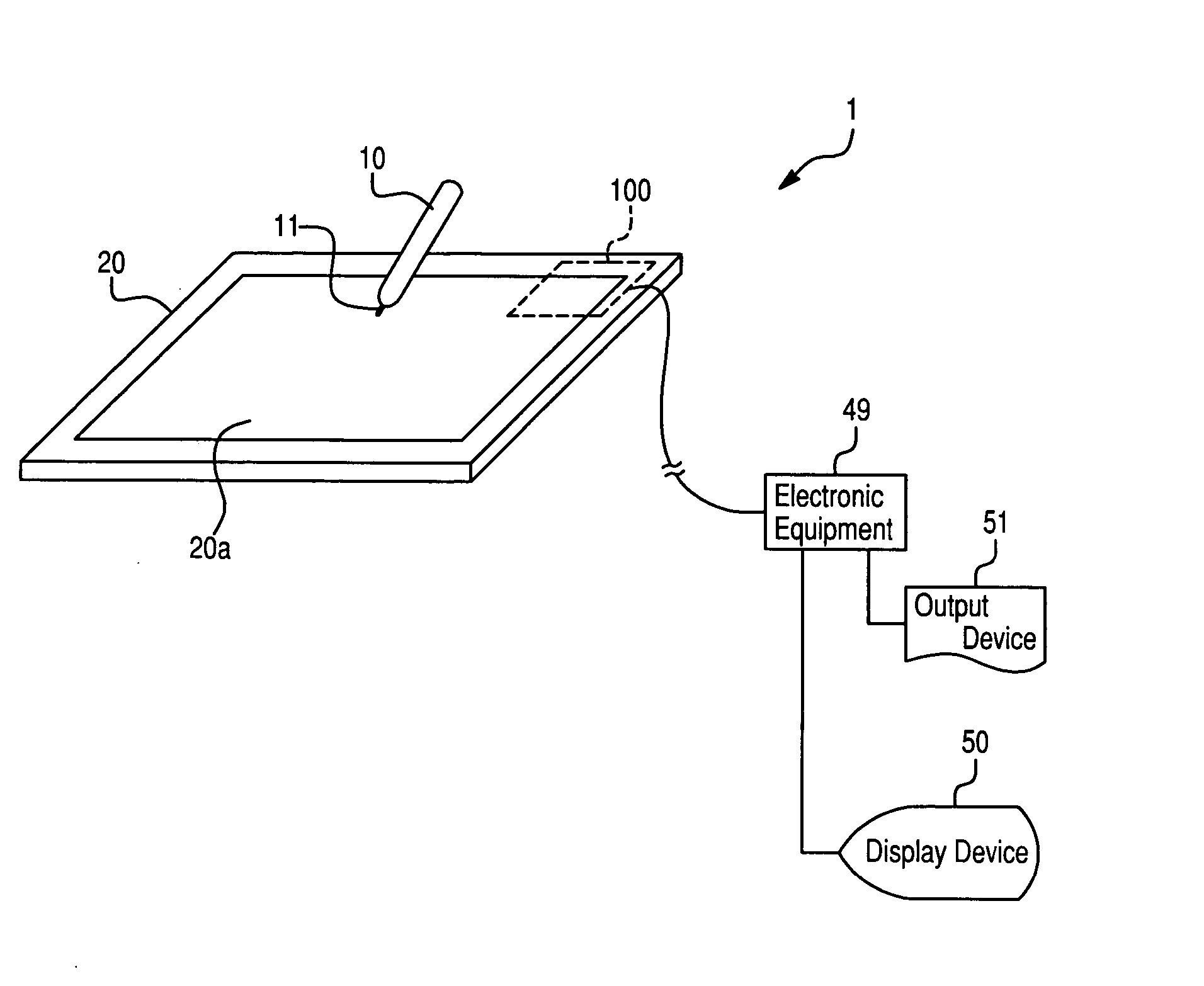
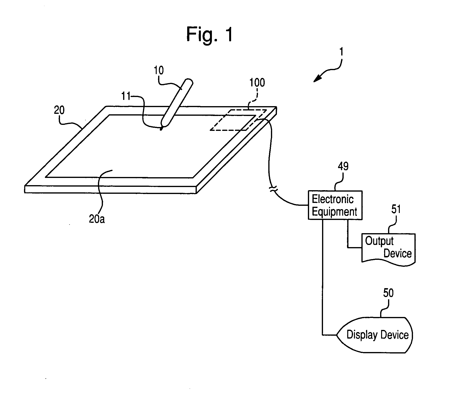
[0049]FIG. 1 shows in summary the configuration of a coordinate input device, as a position input device of an aspect to which this invention is applied. As shown in FIG. 1, the coordinate input device 1 comprises an input pen (coordinate indicator) 10, which the user holds in his hand to operate the device, and a tablet 20 having an operation surface 20a, which serves as an operation base.

[0050] The input pen 10, serving as the position indicator, is of a shape which mimics a ballpoint pen or other general stylus; a core 11 protrudes at the tip. The user holds the input pen 10 in his hand and presses the core 11 against the operation surface 20a of the tablet 20 while moving the pen to perform an operation.

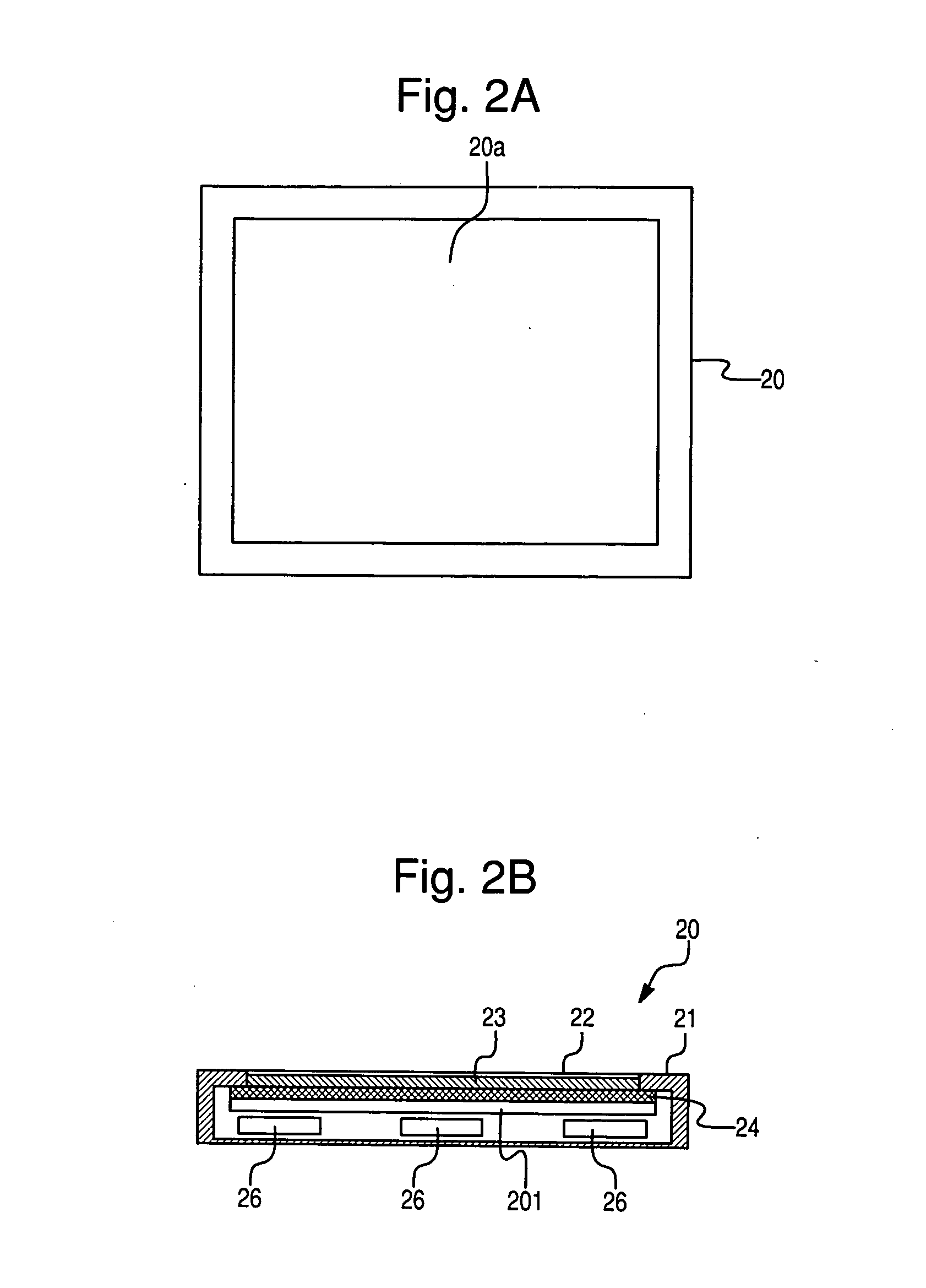
[0051] The tablet 20, serving as the position detection device, detects the position of the input pen 10 on the operation surface 20a, and, when the core 11 of the input pen 10 is pressed down ...


PUM


Abstract

In a position detection device which detects a position indicated by a position indicator, improvements are made such that signals can be received precisely and reliably even at the end portions of the detectable region. In a tablet 20 which detects the position of an input pen 10 by means of electromagnetic inductive action with the input pen 10, a shield plate is positioned below a sensor substrate having a plurality of coils, and a shield layer of a ferromagnetic material is provided to overlap with the shield plate.

Description

BACKGROUND OF THE INVENTION [0001] 1. Field of the Invention [0002] This invention relates to a position detection device to detect a position indicated by a position indicator, and a position input device comprising this position detection device. [0003] 2. Background of the Invention [0004] In the past, position input devices are known which are called pen tablets and comprise a pen-type position indicator and a substantially plate-shaped position detection device. This position input device utilizes the electromagnetic coupling between the position indicator and the position detection device to send and receive weak signals. In recent years, in order to improve the ease of use of position detection devices, there have been demands for more precise and reliable signal transmission and reception between the position indicator and the position detection device. A method has been proposed in which a shield plate is added to the sensor substrate of the position detection device to dim...

Claims


Application Information

Patent Timeline
Patent Type & Authority Applications(United States)
IPC IPC(8): G01B7/14G01B7/30
CPCG06F3/03545G06F3/047G06F3/046G06F3/0416G06F3/04162
Inventor FUKUSHIMA, MASAMITSUHORIE, TOSHIHIKO
Owner WACOM CO LTD
Why Eureka
Try Eureka