Spinal prostheses

a technology of spine and prosthesis, applied in the field of spine prosthesis, can solve the problems of patient loss in part or whole, loss of rotational freedom, and inability to turn the head,

Inactive Publication Date: 2009-06-11
WANG DAJUE
View PDF8 Cites 7 Cited by
  • Summary
  • Abstract
  • Description
  • Claims
  • Application Information

AI Technical Summary

Problems solved by technology

The result is that in addition to the loss of shock absorption in the affected vertebra, there is loss of rotational freedom too with the consequence that the patient loses in part or altogether, the ability to turn the head.

Method used


Image

  • Spinal prostheses
  • Spinal prostheses
  • Spinal prostheses

Examples


Embodiment Construction

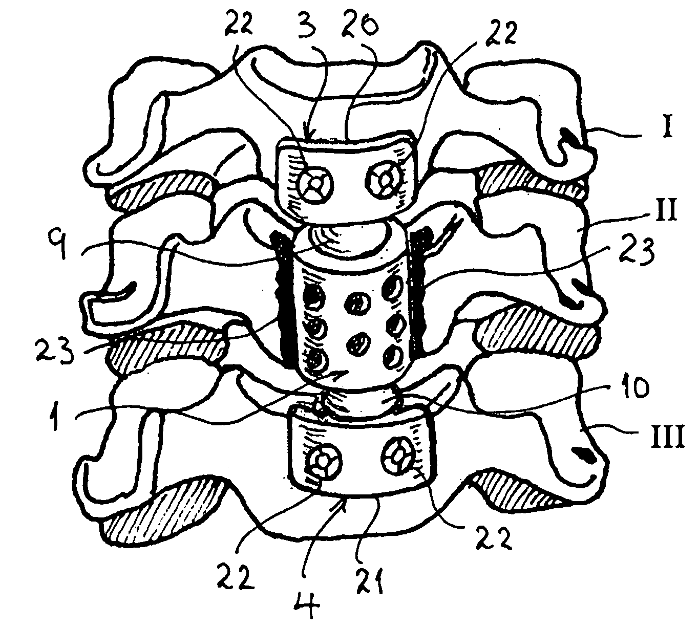
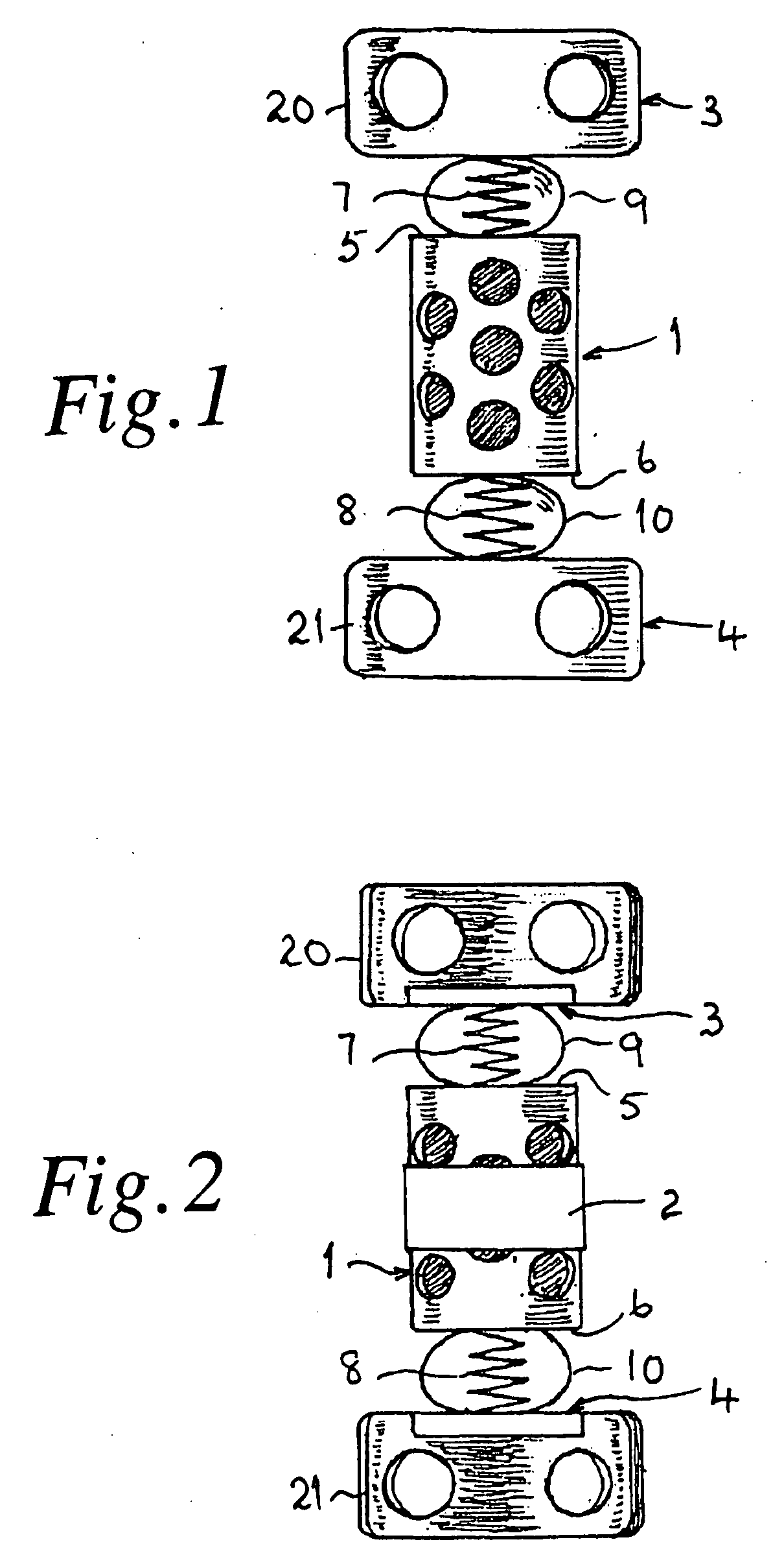
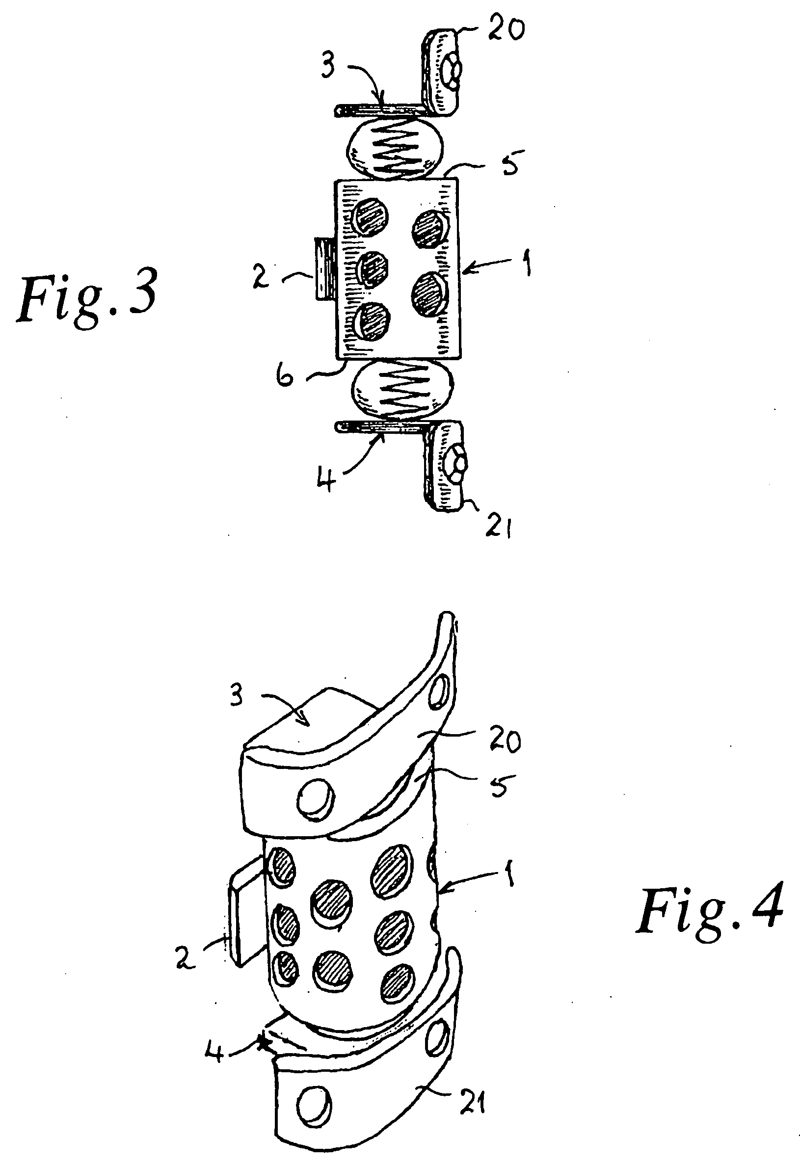
[0013]Referring to FIGS. 1 to 4 the spinal prosthesis, which in this case is for replacement of a fractured or otherwise damaged cervical vertebra and its discs, involves a prosthetic vertebral body in the form of a hollow, metal cylinder 1 of circular cross-section having a perforated wall. An elongate anchor lug 2 (FIGS. 2 and 4) is secured to the rear of the cylinder 1 to extend transversely of it, and anchor plates 3 and 4 are attached to end-caps 5 and 6 respectively of the cylinder 1 via individual, coiled compression-springs 7 and 8. The springs 7 and 8 are moulded into respective beads 9 and 10 of silicone rubber.

[0014]Before the prosthetic assembly is implanted, the cylinder 1 is filled with natural bone chips or bone-substitute material, and is closed by screwing or bonding the end-caps 5 and 6 to either end. Additionally, an anterior portion of the damaged vertebra is cut away to accommodate the cylinder 1, and the superior and inferior intervertebral discs are removed. A...


PUM


Abstract

A spinal prosthesis has a prosthetic vertebral body in the form of a hollow cylinder (1) with perforated wall and attached prosthetic intervertebral discs formed by springs (7,8) moulded into silicone-rubber beads (9,10). Anchoring of the cylinder (1) to the damaged vertebra (II) is by means of entrapment of an elongate lug (12) of the cylinder 1 within a slot (16) of a plate (11) retained by screws (12) within a recess (13) of the damaged vertebra (II). The springs (7,8) of the resilient beads (9,10) are attached to the natural vertebrae (I,III) superior and inferior to the damaged vertebra (II) by fixing plates (3,4) which have flanges (20,21) that are held by screws (22) to those vertebrae (I,III). Where adjoining vertebrae are damaged, two or more prosthetic cylinders (1) for anchoring to the individual vertebra are used with interconnecting resilient beads (9;10).

Description

[0001]This application is a national stage completion of PCT / GB2005 / 004486 filed Nov. 21, 2005 which claims priority from British Application Serial No. 0425546.9 filed Nov. 20, 2004.FIELD OF THE INVENTION[0002]This invention relates to spinal prostheses.SUMMARY OF THE INVENTION[0003]According to the present invention there is provided a spinal prosthesis comprising a prosthetic vertebral body having means for attaching it to a subject vertebra, two resilient elements attached to opposite ends of the prosthetic vertebral body to provide respectively prosthetic intervertebral discs between the subject vertebra and the vertebrae superior and inferior to it, and means for attaching the resilient elements to their respective superior and inferior vertebrae.[0004]The spinal prosthesis of the invention is of a form that is readily applicable to replacement of cervical, lower thoracic and lumbar vertebrae and their discs, that have been damaged by fracture or disease. It is of especial adv...

Claims


Application Information

Patent Timeline
Patent Type & Authority Applications(United States)
IPC IPC(8): A61F2/44A61B17/58A61F2/00A61F2/28A61F2/30
CPCA61F2/30744A61F2230/0069A61F2002/2835A61F2002/30069A61F2002/30235A61F2002/30388A61F2002/30476A61F2002/30563A61F2002/30566A61F2002/30578A61F2002/30784A61F2002/4475A61F2002/449A61F2220/0025A61F2/44A61F2002/30387A61F2002/30593A61F2/442
Inventor WANG, DAJUE
Owner WANG DAJUE
Why Eureka
Try Eureka