Eureka AIR delivers breakthrough ideas for toughest innovation challenges, trusted by R&D personnel around the world.

Plumb probe assembly for a level measuring device

Inactive Publication Date: 2009-06-18
FINETECK
View PDF12 Cites 0 Cited by
  • Summary
  • Abstract
  • Description
  • Claims
  • Application Information

AI Technical Summary

Benefits of technology

[0008]The main objective of the present invention is to provide a plumb probe assembly for a level measuring device to prevent a motor of a controlling assembly and a particulate discharging device from being damaged.
[0010]When the plumb is buried in the particulates, a weight that the particulates impose on the plumb is stronger than the clipping force that the connection assembly is held by the connectors. Therefore, the clip brackets separate away from each other and the plumb falls into the container. The plumb will not cause damage to the particulate discharging device and will disconnect with the connection assembly. People may then mount another plumb to the connection assembly inner connecting tube for continual functioning of the level measuring device.

Problems solved by technology

However, if the conventional plumb probe assembly is buried by particulates in the container, the motor might overload the line, causing the conventional plumb probe assembly to break off or a weight of the particulates becomes larger than the pulling force of the motor, the line cannot be wound, both effectively turning the particulate discharging device into a permanent on state.
Alternatively, stirrers of the particulate discharging device might engage the conventional plumb probe assembly or line, pulling the line and causing damage to the particulate discharging device or tangling the line on the stirrer and turning the particulate discharging device permanently on.
Finally, the particulate discharging device can only add particulates to the container and cannot remove particulates from the container.
Therefore, any above situation would cause overfilling, leading to a waste of particulates, an increase in cleaning costs and could lead to reduced production or even factory closure.

Method used


Image

  • Plumb probe assembly for a level measuring device
  • Plumb probe assembly for a level measuring device
  • Plumb probe assembly for a level measuring device

Examples


Embodiment Construction

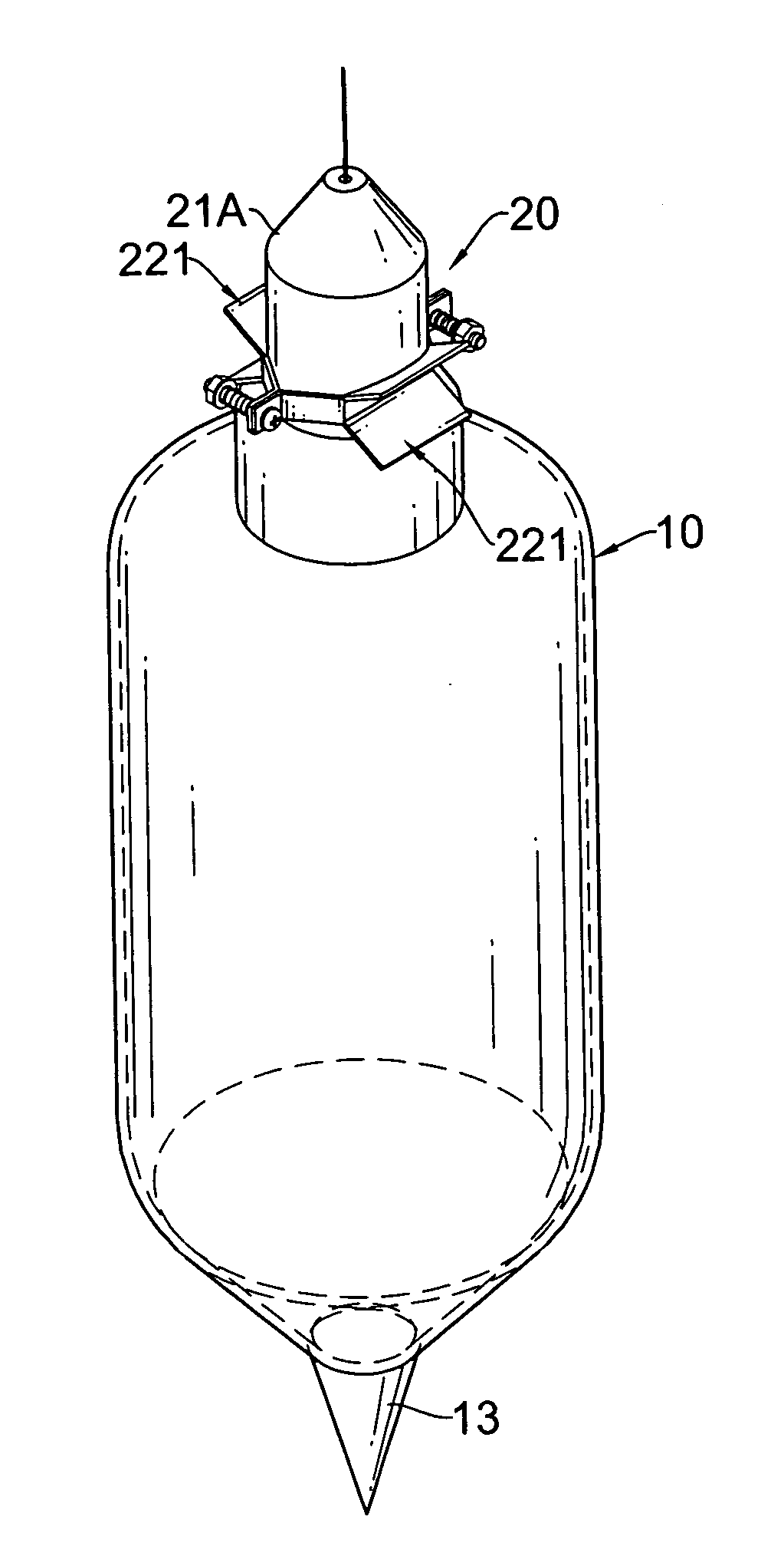
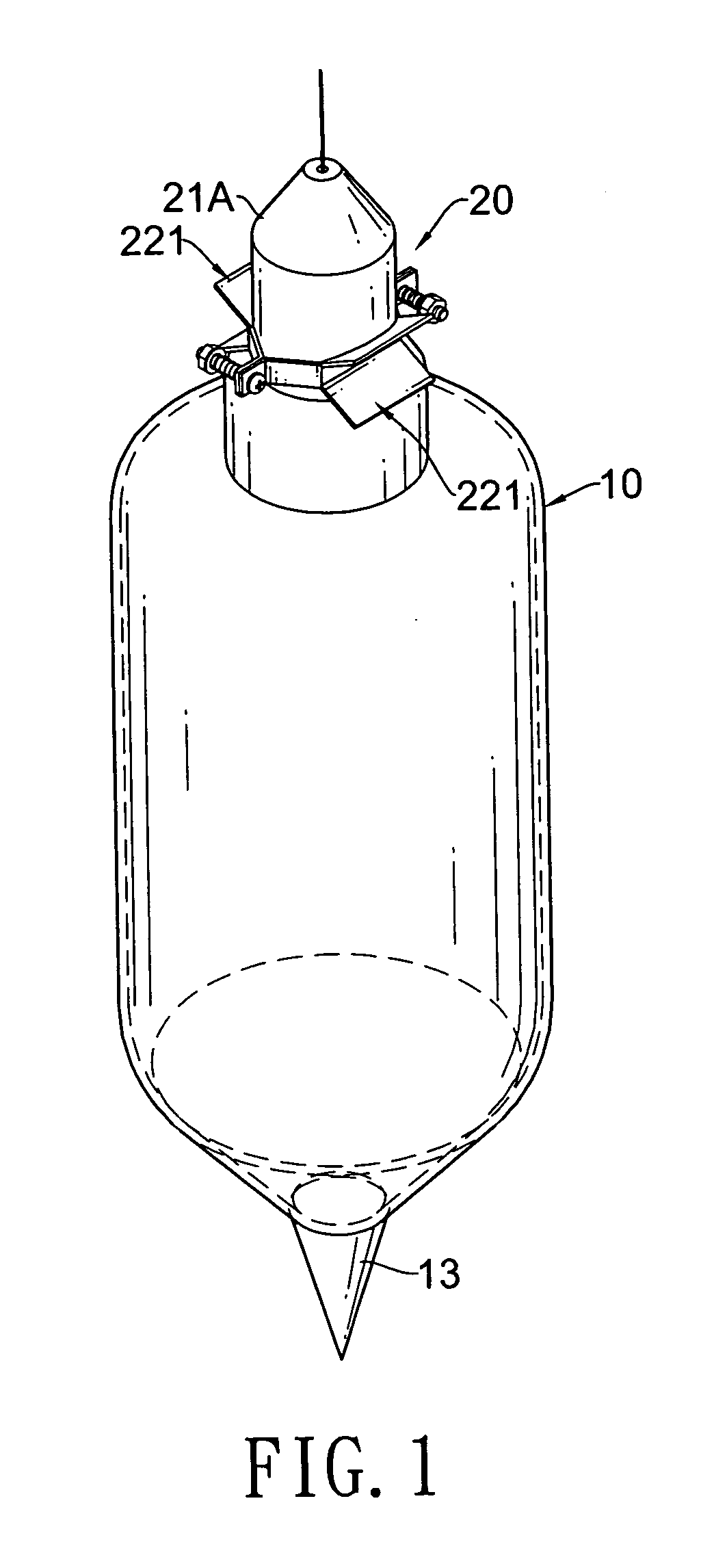
[0020]With reference to FIGS. 1 and 4, a level measuring device comprises a controlling assembly (30) and a plumb probe assembly in accordance with the present invention. The controlling assembly (30) comprises a spool (31), a line (32) and a motor. The line (32) is wound around the spool (31) and has a distal end. The motor is connected to and rotates the spool (31) to allow the spool (31) to selectively wind or unwind the line (32). The plumb probe assembly is connected to the distal end of the line (32) and comprises a plumb (10) and a connection assembly (20).

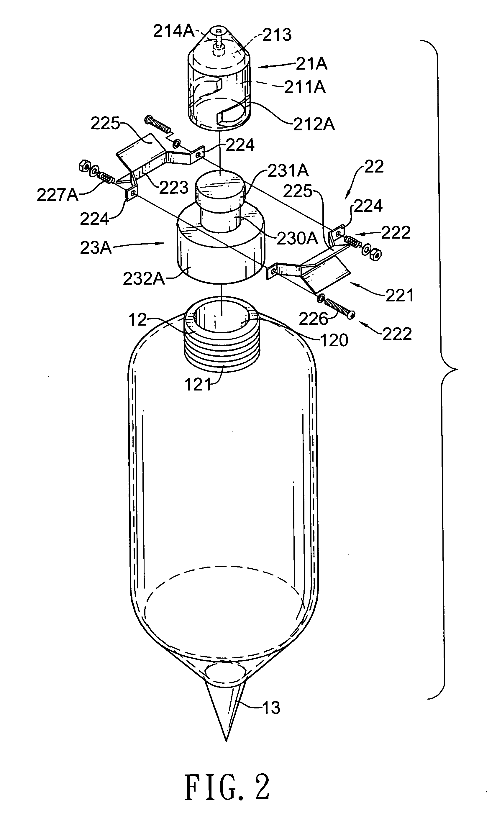
[0021]With further reference to FIG. 2, the plumb (10) is plastic, hollow, breakable and has a bottom, a top, an optional tip (13) and an inner connecting tube (12). The tip (13) is formed on and protrudes coaxially from the bottom of the plumb (10). The inner connecting tube (12) is formed on and protrudes coaxially from the top of the plumb (10) and has an outer surface, a through hole (120) and an optional external threa...


PUM


Abstract

A plumb probe assembly for a level measuring device has a plumb and a connection assembly. The plumb has an inner connecting tube. The connection assembly has two connectors and two clip brackets. The connectors are slidably mounted together while one of the connector firmly connects to the inner connecting tube of the plumb. The clip brackets are movably connected together by at least one resilient device supplying a clipping force and clip around the connectors to hold connectors firmly together. When a force greater than the clipping force, applied to the plumb, the clip brackets separate and the plumb falls into the particulates in the container. The plumb will not cause damage to a particulate discharging device and will disconnect with the connection assembly. A replacement plumb may then be attached to the connection assembly for continued operation.

Description

BACKGROUND OF THE INVENTION[0001]1. Field of the Invention[0002]The present invention relates to a measuring device, especially to a plumb probe assembly for a measuring device that detects heights of particulates added to a container.[0003]2. Description of the Prior Arts[0004]Particulates including, but not limited to animal feeds, cements, plastic grains or corns comprising grains, lumps and powders are stored in containers. The container has a top, a bottom, a level measuring device and a particulate discharging device. The level measuring device is mounted on the top of the container to detect a fill level of the particulates and has a controlling assembly and a conventional plumb probe assembly. The controlling assembly has a spool, a line and a motor. The line is wound around the spool and has a distal end. The motor connects to and rotates the spool to allow the spool to selectively wind or unwind the line. The conventional plumb probe assembly is metal and connects to the d...

Claims


Application Information

Patent Timeline
IPC IPC(8): G01C15/10
CPCG01F23/0023
Inventor WU, DICK
Owner FINETECK
Why Eureka
Eureka Blog
Learn More