Mechanically collapsible core for injection molding

a core device and injection molding technology, which is applied in the direction of coatings, manufacturing tools, applications, etc., can solve the problems that the core is not easily removed from the article after the article, and injection molding is not conducive to the production of hollow objects, etc., and achieve the effect of easy removal from the molded par

Inactive Publication Date: 2009-06-18
CANON VIRGINIA
View PDF2 Cites 50 Cited by
  • Summary
  • Abstract
  • Description
  • Claims
  • Application Information

AI Technical Summary

Benefits of technology

[0017]The additional collapsible core members may be referred to as second collapsible core members and they each have an engaging member, such as a rail, that engages with a respective engaging member (or groove) of the base member. The rails of the second collapsible core members and the grooves in the conical surface of the base member act to allow the second collapsible core members to translate both inward and lengthwise simultaneously.
[0018]Thus, when the device is assembled at a home position, the central pin is slidably engaged into an orifice of the base member, the first collapsible core members are inserted into the cutouts of the base member with the rails of the first collapsible core members being engaged with the grooves of the central pin inserted through the orifice, and the rails of the second collapsible core members are engaged with the grooves in the conical portion of the base member with a first end of the second collapsible core members engaging the shoulder portion of the base member. The central pin is inserted through the orifice to a depth such that the first end of the pin, a first end of each first collapsible core member, a first end of the base member, and a first end of each second collapsible core member are substantially even, whereby a second end of each first collapsibl

Problems solved by technology

However, to date, injection molding has not been conducive for the production of hollow articles, and particularly for hollow articles that have an internal undercut near the opening.
Since the article is h

Method used


Image

  • Mechanically collapsible core for injection molding
  • Mechanically collapsible core for injection molding
  • Mechanically collapsible core for injection molding

Examples


Embodiment Construction

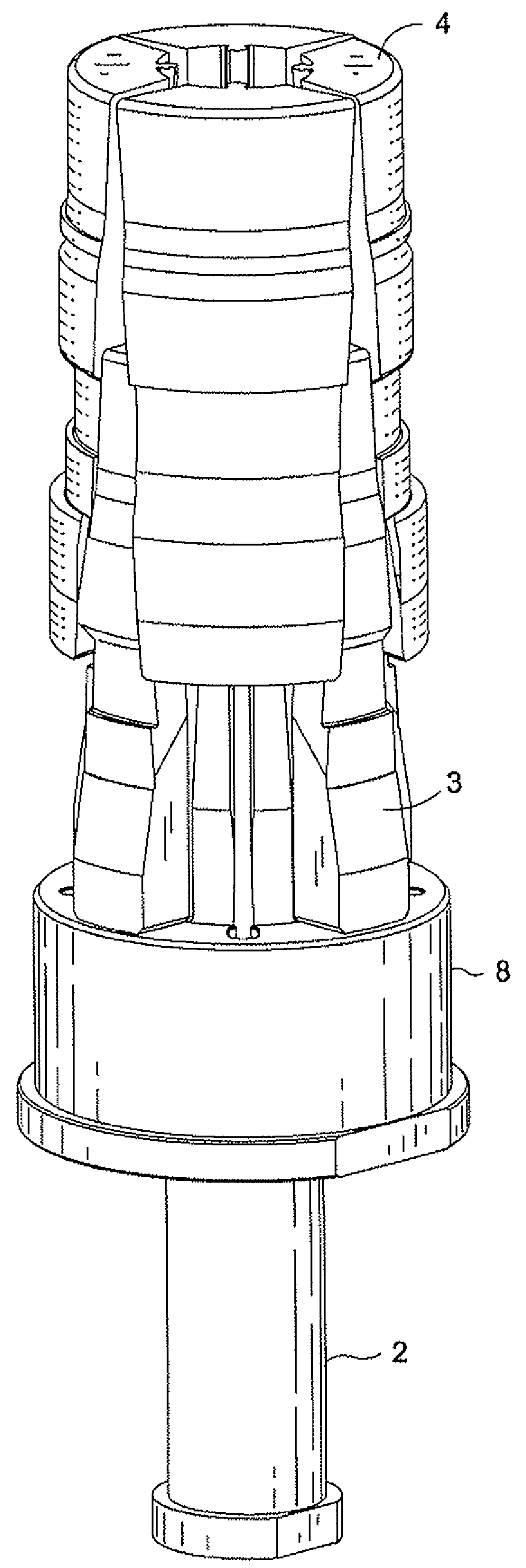
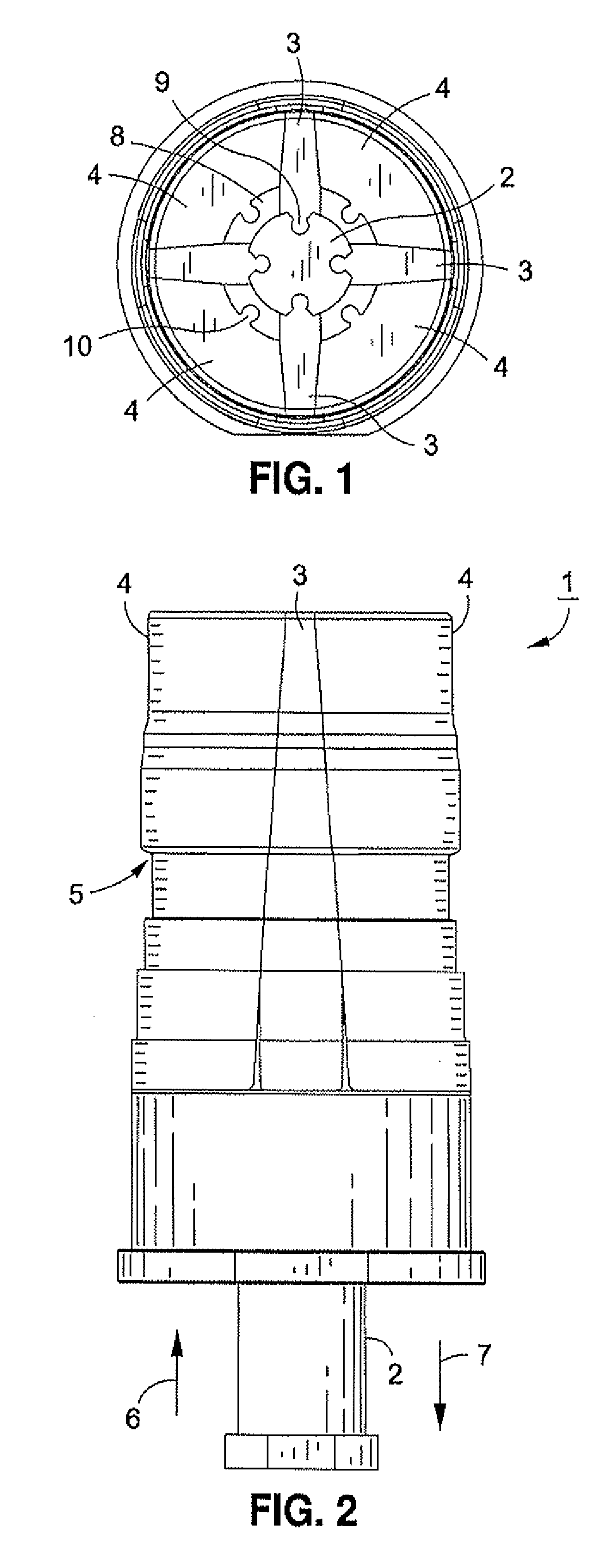
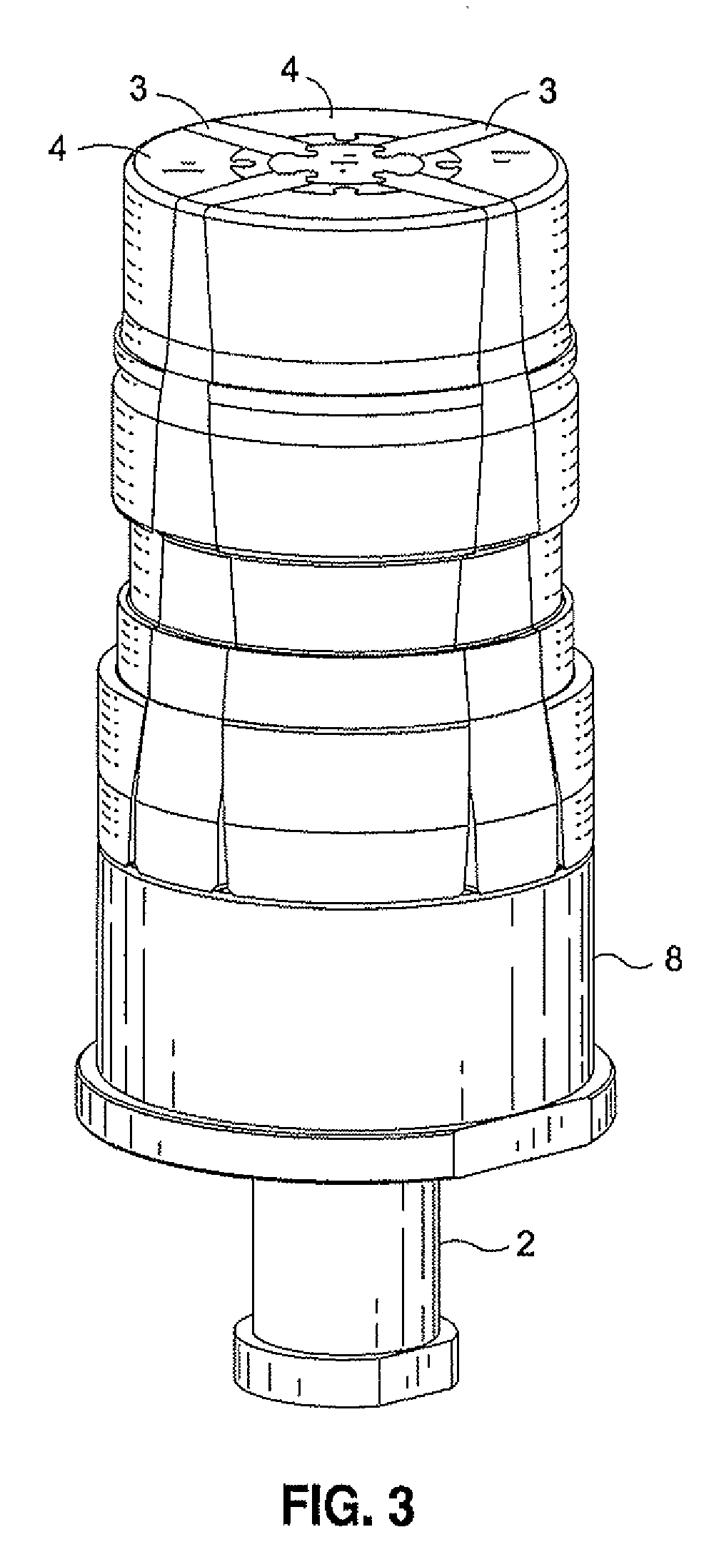
[0040]In FIGS. 1 and 2, a mechanically-collapsible core device 1 according to the invention is seen to include a central pin 2, a plurality of first collapsible core members 3 and a plurality of second collapsible core members 4. The precise external shape of the mechanically-collapsible core device is, of course, dependent upon the internal surface design of the part being molded. Thus, the external shape shown in the drawings is merely representative of one article of manufacture. However, one object of the invention is to provide a mechanically-collapsible core device that can be easily removed from articles that include an internal undercut. In FIG. 2, reference numeral 5 depicts an undercut in the article being molded. For instance, the undercut may be a lip in a part.

[0041]In operation, mechanically-collapsible core device 1 is inserted into another portion of a molding fixture which forms the exterior surface of the article. When the core assembly is ready to be inserted into...


PUM

PropertyMeasurementUnit
Timeaaaaaaaaaa
Diameteraaaaaaaaaa
Lengthaaaaaaaaaa

Abstract

The invention relates to a mechanically-collapsible core device includes a central pin having a plurality of engaging members, a plurality of first collapsible core members each having an engaging member that engages with a respective engaging member of the central pin, a base member having a plurality of engaging members, and a plurality of second collapsible core members each having an engaging member that engages with a respective engaging member of the base member. The pin is retracted from a home position, thereby causing the first core members to collapse inward. The base member is then retracted, thereby causing the second core members to translate inward and linearly. The result is that the core device collapses inward in size so as to permit the device to be removed from the inside of a molded article.

Description

CROSS-REFERENCE TO RELATED APPLICATION[0001]This application claims priority under 35 U.S.C. § 119(e) to provisional Application No. 60 / 954,554, filed on Aug. 7, 2007, the contents of which are incorporated by reference as if set forth in full herein.BACKGROUND OF THE INVENTION[0002]1. Field of the Invention[0003]This present invention relates to core devices for injection molding processes, and in particular, relates to a mechanically-collapsible core device for use in injection molding of articles having a distinct undercut.[0004]2. Related Background Art[0005]In the field of molding hollow plastic articles, blow molding has been the preferred method of manufacturing such articles. The most commonly known types of blow molding procedures are extrusion blow molding, injection blow molding, and stretch blow molding. In extrusion blow molding, plastic is melted and extruded into a hollow tube (a parison). This parison is then captured by closing it into a cooled metal mold. Air is th...

Claims


Application Information

Patent Timeline
IPC IPC(8): B29C45/40
CPCB29C45/4421
Inventor MIKAC, PAUL ROBERTSTRAIN, DALE ROBERT
Owner CANON VIRGINIA
Why Eureka
Try Eureka