Product display tray with pull through feature

a technology of product display and pull-through, which is applied in the direction of instruments, apparatus for dispensing discrete objects, de-stacking articles, etc., can solve the problems of difficult or impossible normal upward removal of packages, difficult for some customers, and difficult to handle products of this type, so as to facilitate the removal process of packages and facilitate the deflecting

Active Publication Date: 2012-11-06
TRION IND
View PDF53 Cites 14 Cited by
  • Summary
  • Abstract
  • Description
  • Claims
  • Application Information

AI Technical Summary

Benefits of technology

[0007]In accordance with one aspect of the invention an improved form of display tray is provided, for packaged sandwich meats and the like, which incorporates a novel and improved form of package-retainer, arranged to engage opposite side edge margins of the package back panel while allowing blister portion to project forwardly at the front of the display. The top of the package back panel is not restrained and is free to be engaged by a customer's hand. A customer desiring to extract a package from the display thus can grip the unrestrained upper portions of the package and pull forwardly. The normally restrained lower side edge portions of the package back panel are easily deflected and enabled to pass through the retainer and removed by the customer. The ability of the customer to engage and pull forward on the top of package makes the package removal process much easier than gripping the package by its forwardly projecting blister and pulling the margins of the package through a more conventional retaining frame.
[0008]In a particularly advantageous form of the invention, package retainer elements formed integrally and in one piece with forward portions of spaced apart wire side guide elements which extend longitudinally on each side of the display tray for lateral confinement of the packages. The wire side guide elements define guide planes for lateral confinement of a front-to-back column of packages. At their forward ends, the wire side guide elements are bent downwardly, preferably in a generally vertical plane, and portions thereof are displaced laterally inward to engage opposite side edge portions of the back panel of the forwardmost package on the tray. These downwardly and inwardly bent portions thus form a retainer for the forwardmost package of a column. The extent of inward displacement of the retainer portions is such as to allow the blister portion to project forward of the vertical plane of the retainer. To particular advantage, the inwardly displaced retainer portions extend inward and downward at a shallow angle to the vertical. Thus, when the front package is grasped by the upper portion of its back panel and pulled forward, the downwardly and inwardly angled wire retainer portions gradually deflect the package edges laterally and allow the package to be easily pulled through the retainer structure and withdrawn from the tray.
[0009]In another advantageous version of the tray, in which the side walls of the tray are formed of a rigid sheet material, an integral retainer structure is provided by the inward displacement of small retaining tabs of the sheet material near the front of the tray. The retaining tabs engage side edges portions of the back panel of the forwardmost package on the tray and form a retaining structure, while allowing the product-containing blister to project through. A package can easily be removed from the tray by gripping the upper edge of its back panel and pulling forward. As the upper portion of the package is tilted forward, the side edges thereof are displaced inwardly by the retaining tabs. This enables the package to be easily withdrawn from the tray by the customer, as desired.
[0010]In yet another embodiment of the new tray, where the tray is formed with laterally spaced side guides formed of sheet material, a package retaining structure is formed by a pair of retaining elements of inverted U-shaped configuration extending upward from the a bottom structure of the tray and positioned to engage opposite side edges of a package at the front of a front-to-back column thereof. The top of the front package is unobstructed and readily gripped by a customer desiring to extract the package. The customer pulls forward on the top of the package, causing the side edges of its back panel to be displaced inwardly by generously rounded upper ends of the retaining elements. This enables the package to be easily passed between the retaining elements and withdrawn by the customer. In accordance with the invention, the retaining elements are formed of wire into the desired inverted U-shaped configuration. The arrangement is such that the raw end of the wire is concealed and protected against, or closely adjacent to, the inside of the side guides, and the only exposed parts of the wire are the generously rounded upper end portions thereof.
[0011]In any of the forms of the invention, the package retaining elements are of a height to terminate well below upper edges of the package back panels and preferably below the tops of the blisters. The retaining elements thus engage package edges in central portions thereof. When a package is engaged by its unobstructed upper portion by a customer, the package can be easily pulled forward while its lower side wall portions are deflected inward for passage between the retaining elements.
[0012]Optionally, the retaining structure of the display tray, in any of its forms, can be spaced rearward of the front extremity of the tray, such that there is a space equal to at least one package thickness in front of the projecting blister portion of a retained, forwardmost package. Store keepers frequently desire to provide such a space because a customer may change his or her mind after extracting a package and need a place to return it. Returning an extracted package of this type to a position behind the retaining structure usually is difficult because of the typically nested character of the packages and because there may be little to no overhead clearance above the tray to enable the package to be returned. The extra space at the front allows a customer to return the package to the tray, as the new forwardmost item, where the package is adequately displayed and can easily be taken by the next customer.

Problems solved by technology

Products of this type tend to be difficult to handle in typical push-forward type display trays because the nesting of adjacent packages, coupled with limited overhead spaces, makes the normal upward removal of a package difficult or impossible.
This may be difficult for some customers.
Another problem with known display trays of the type mentioned above is that, whenever a customer removes a package and then changes his or her mind (a not-infrequent occurrence), dealing with the removed but unwanted package presents a problem.
In the end, the customer may just place the package in an improper location, wherever space can be found.

Method used


Image

  • Product display tray with pull through feature
  • Product display tray with pull through feature
  • Product display tray with pull through feature

Examples


Embodiment Construction

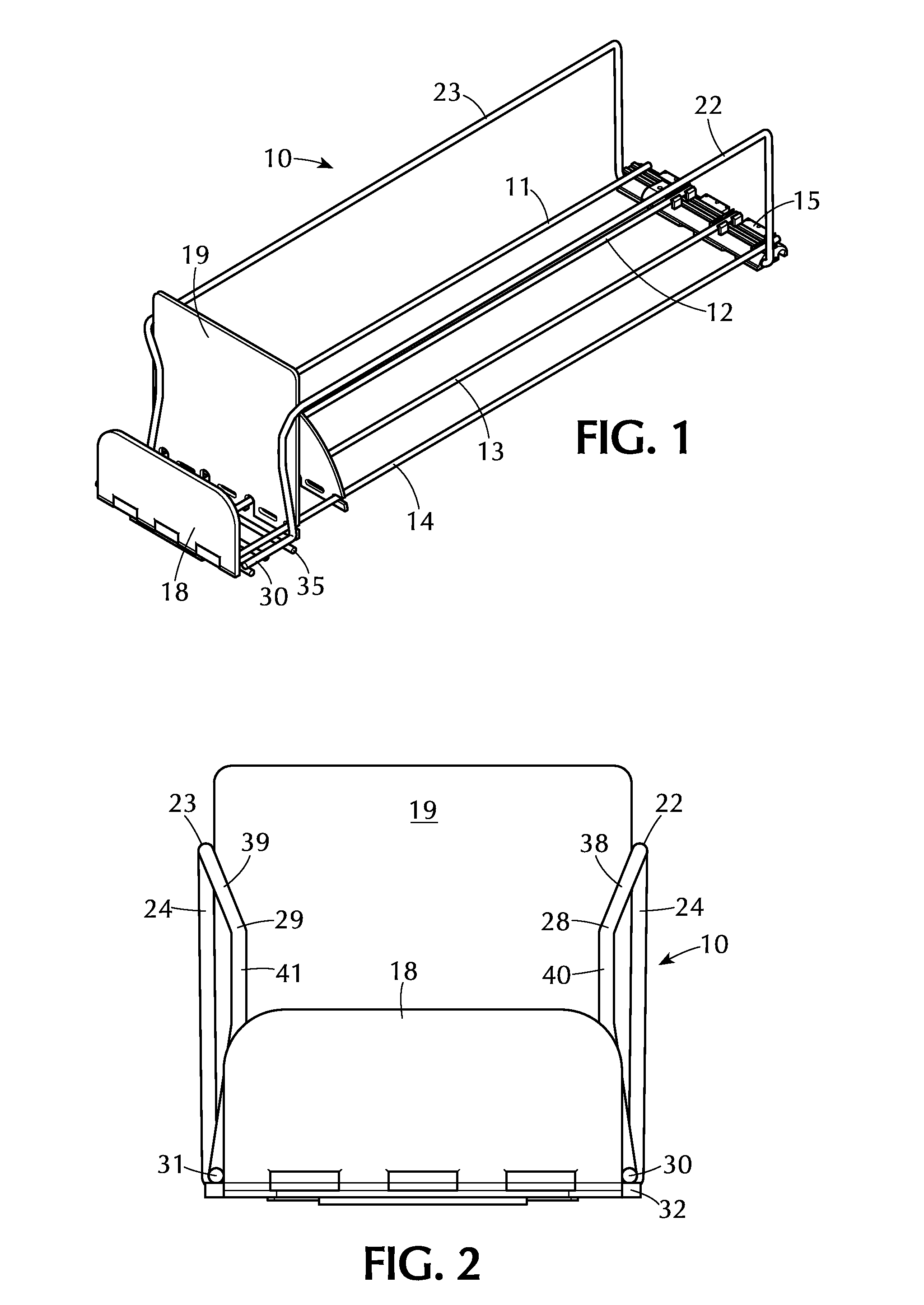
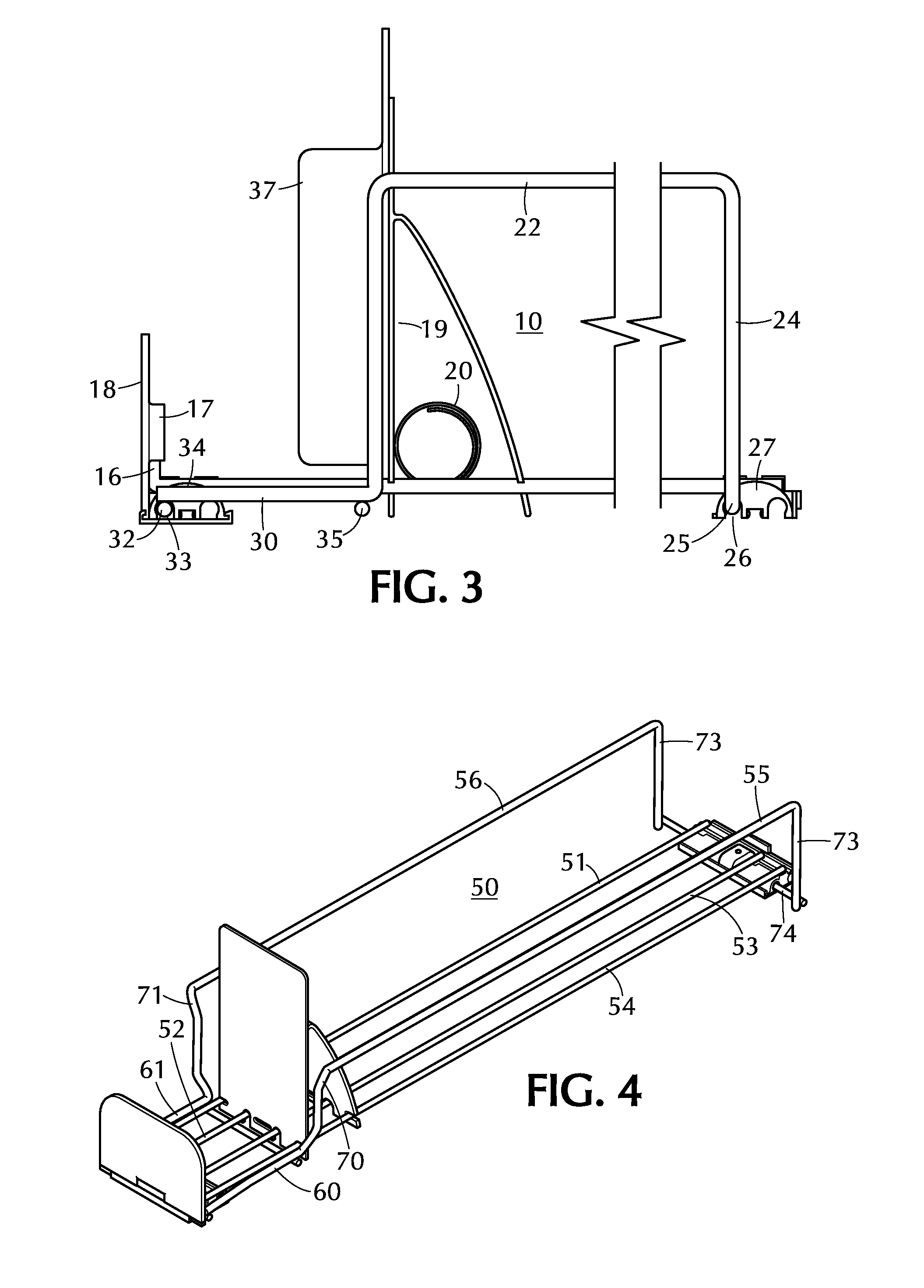
[0025]Referring now to the drawing, and initially to FIGS. 1-3 thereof, the reference numeral 10 designates generally a preferred form of product display tray in which the features of the invention are advantageously incorporated. Features of such display trays are shown in U.S. Pat. Nos. 6,745,906, 6,866,155, 6,866,700, 6,889,855 and 7,032,761, and the disclosures of these patents are incorporated herein by reference. In the illustrated form of tray, shown best in FIGS. 1 and 2, there is a tray base structure formed of four longitudinally extending wires 11-14. These longitudinally extending wires are joined at their back edges by a rear cross bar 15. At the forward end of the wire base structure there is a front cross bar (not shown) which is fixed to the forward ends of the two internal wires 12, 13 and is fixed to the outside wires 11, 14 adjacent the forwardmost end portions thereof. In the illustrated tray, the forward extremities 16 of the outer wires 11, 14 are bent upwardly...


PUM


Abstract

A tray for the display and dispensing of products in blister packages. Side guide elements, of wire or sheet material, are provided in forward portions thereof with retaining elements formed integrally and in one piece therewith. The retaining elements engage side margins of a forwardmost package well below the tops of the packages and preferably below the tops of the blisters thereof. A forwardmost package is gripped by its exposed and unobstructed upper portions and pulled forwardly to remove a package. Integral, one-piece construction of the side guide elements and the retaining elements provides for economical manufacture with superior performance. Optionally, space may be provided in front of the retaining portions to accommodate return of packages by a customer who has changed his or her mind. In one embodiment, a wire retaining portion of inverted U-shaped configuration is positioned with wire ends concealed and protected by the tray side.

Description

CROSS-REFERENCE TO RELATED APPLICATIONS[0001]The present application claims the benefit under 35 U.S.C. §119(e) of the U.S. Provisional Patent Application Ser. No. 61 / 228,051, filed on Jul. 23, 2009, the content of which is incorporated herein by reference. The present application is also related in subject matter to our co-pending application Ser. No. 12 / 354,366, filed Jan. 15, 2009.FIELD OF THE INVENTION[0002]The invention relates to product display trays, particularly for the display of packaged sandwich meats and the like sold in blister packs.BACKGROUND OF THE INVENTION[0003]In the store display of small product items, it is a common practice to provide display trays arranged to receive a plurality of product items in a front-to-back column, with a spring actuated pusher paddle at the back of the column arranged to automatically move the column forward each time a product item is removed from the front of the display. This makes for a more sales-attractive display, by keeping t...

Claims


Application Information

Patent Timeline
Patent Type & Authority Patents(United States)
IPC IPC(8): A47F1/04
CPCA47F1/126
Inventor NAGEL, THOMAS O.KOLOGE, JOSEPH F.
Owner TRION IND
Why Eureka
Try Eureka