Sandwich arrangement with ceramic panels and ceramic felts

Inactive Publication Date: 2018-03-08
ANSALDO ENERGIA IP UK LTD
View PDF1 Cites 15 Cited by
  • Summary
  • Abstract
  • Description
  • Claims
  • Application Information

AI Technical Summary

Benefits of technology

[0040]Based on this set-up, it is easily possible to achieve the hole-diameter and correct angle of single CAH's (Cooling Air Hole) given by the design and to avoid a potential damaging of the fibres and/or woven CMC structure. In a subsequent step, the wrapped CMC material is infiltrated by a slurry technique, or impregnated by CVD or other method, or otherwise combined with the ceramic matrix material and finally (semi-)fired. The described steps can be repeated until reaching the intended CMC wall thickness needed for the individual IGT part section. The pins are inserted between the fibres of the textile going through the textile thickness without damaging the fibres but enabling the formation of holes that will be used as cooling holes. The pins are fixed into the mould in predetermined positions/anchoring holes
[0041]After the drying of the CMC form around the mould, the pins can be removed, the CMC piece can b

Problems solved by technology

Typical drawbacks of today's standard monolithic ceramic and CMC systems in modular IGT component designs:1. Brittle behaviour and low fracture toughness (monolithic ceramic).2. Very limited fatigue behaviour, especially monolithic ceramic, but also CMC systems.3. Limit creep resistance (CMC).4. Cost intensive (CMC).
Commercially available, as well as in literature described CMC material still suffers from:Mechanical strength values of CMCs which are generally at the limit of the design requirements, when considering turbine parts and especially in case of rotating blading (creep loading).
Considering a simple functional split (i.e., mechanical and thermal decoupling) of the different component sections, such as, splitting the component into different subcomponents, where certain areas have mainly to sustain the mechanical load and other component sections will have to resist to a high thermal loading (as mentioned in several patents and open literature) is not sufficient.
Especially in the case of a need for thicker

Method used


Image

  • Sandwich arrangement with ceramic panels and ceramic felts
  • Sandwich arrangement with ceramic panels and ceramic felts
  • Sandwich arrangement with ceramic panels and ceramic felts

Examples


Example

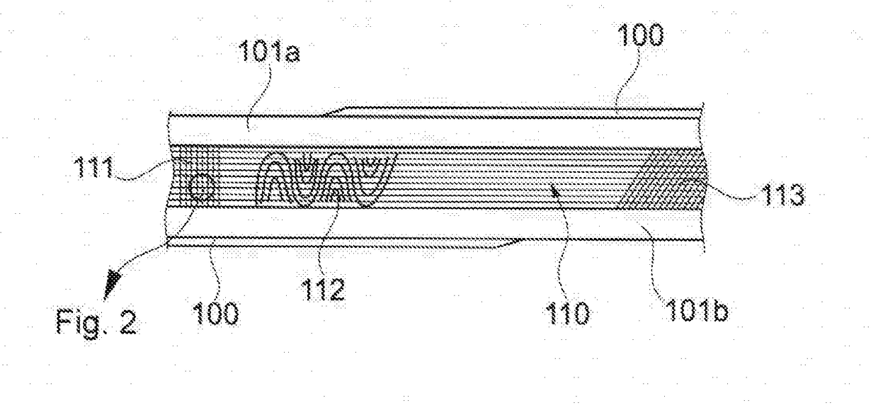
[0093]FIG. 1 shows a partial longitudinal section through an embodiment of multi-plies CMC provided as a sandwich system. Fundamentally, the embodiment CMC material can be designed with individualized fibre structure in accordance with the operational requirements. A certain percentage of the fibres exhibits differentiated diameters, which are intended to mainly carry the mechanical load (in the case of the larger diameters) within the CMC section of the hot gas path parts during operation. The outermost panels 101a, 101b of the sandwich system (100, 101a, b, 110, . . . ) consist of one or more plies, wherein at least one of the panel 101 possesses an integral or quasi-integral smooth protective coating 100 having a strong contact with the adjacent ceramic structure of the panel. In many applications, but not exclusively, it is preferably that the fibres of the first panel 101a have the same composition and / or material as the fibres of the second panel 101b, which is disposed on the...


PUM

PropertyMeasurementUnit
Flow rateaaaaaaaaaa
Permeabilityaaaaaaaaaa

Abstract

The disclosure relates to a sandwich arrangement having at least two peripheral disposed ceramic panels and a ceramic felt which is inserted between a first and second ceramic panel, The material of the first ceramic panel is equal or different to the material of the second panel, wherein the ceramic felt is formed by a textile structure with a regularly or quasi-regularly structured woven fibres. The fibres are made of at least one material and/or composition, wherein at least one adhesive is provided between an underside of the panels and adjacent fibres.

Description

TECHNICAL FIELD[0001]The present invention relates to advanced concepts for modular Industrial Gas Turbine (IGT) components, which are based on the principle of using best suited materials for individual sections in every area of IGT components according to the state of the art referring to one of the claims 1 to 5.BACKGROUND OF THE INVENTION[0002]The selection of most adequate material is driven by environmental, thermal, mechanical and thermos-mechanical load conditions under service exposure. According to this design concept, monolithic ceramic and ceramic matrix composite (CMC) materials are especially beneficial to be applied in highly temperature loaded areas, whereas metal alloys are preferentially used mainly in mechanically or thermos-mechanically loaded sections. This principle implicates the utilization of monolithic ceramics and especially CMCs for the generation of platforms and airfoils, inserts or more generally as liner material for the respective sections.[0003]The ...

Claims


Application Information

Patent Timeline
IPC IPC(8): B32B5/02B32B18/00F01D5/28B32B7/12C04B37/00
CPCB32B5/024B32B5/022B32B18/00F01D5/284F01D5/282B32B7/12C04B37/005C04B37/008F01D5/189F01D5/186B32B2260/021B32B2260/023B32B2262/105B32B2262/106B32B2262/14B32B2603/00C04B2235/5256C04B2237/04C04B2237/38C04B2237/597C04B2237/62F05D2300/6012F05D2300/6033F05D2300/613B32B3/04B32B3/28B32B5/08B32B5/142B32B5/145B32B5/26B32B15/02B32B15/04B32B15/14B32B2250/40B32B2255/02B32B2307/304B32B2307/306B32B2307/546B32B2307/714B32B2307/724B32B2607/00B32B1/00C04B2235/6028Y02T50/60
Inventor GRASSO, PIERO-DANIELESTANKOWSKI, ALEXANDERPUIDOKAS, SABRINA
Owner ANSALDO ENERGIA IP UK LTD
Why Eureka
Try Eureka