
Stop module, in particular for automatic machining and conveyor systems

a stop module and automatic machining technology, applied in the direction of conveyors, conveyor parts, transportation and packaging, etc., can solve the problem of relatively high cost of manufacturing such a stop module, and achieve the effect of simple damage structur

Active Publication Date: 2009-06-25
ROBERT BOSCH GMBH
View PDF10 Cites 0 Cited by
  • Summary
  • Abstract
  • Description
  • Claims
  • Application Information

AI Technical Summary

Benefits of technology

[0006]It is the object of the present invention to create a stop module, in particular for automated machining and conveyor systems, in which a motion of a stop element from a first terminal position to a second terminal position can be damped structurally simply and effectively.
[0007]This object is attained with a stop module, in particular for automated machining and conveyor systems, in which a stop element for objects moving in a direction of motion in a movement plane is located on a base body, and in which the stop element is movable by means of a drive device between a first terminal position, in which the stop element protrudes into the movement plane of the objects, and a second terminal position, in which the stop element enables a motion of objects in the movement plane, and in which a damping device cooperating with the stop element is provided, in order to damp a motion of the stop element from a first stop position into a second terminal stop position, which is offset relative to the first stop position at least approximately in the direction of motion of the objects, when an object is resting on the stop element. According to the invention, it is provided that the damping device damps the motion of the stop element from the first stop position to the second terminal stop position with a rotation damper.
[0008]A stop module according to the invention has the advantage that a motion of a stop element from a first terminal position to a second terminal position is damped structurally simply and effectively. It is also advantageous that when objects moving in a direction of motion in a movement plane are stopped by the stop element, only relatively slight forces act on them.

Problems solved by technology

Disadvantageously, the structural complication involved in damping a motion, caused by an object striking the stop member, of the stop member between the first stop position and the second terminal stop position is high, and hence manufacturing such a stop module entails relatively high costs.

Method used


Image

  • Stop module, in particular for automatic machining and conveyor systems
  • Stop module, in particular for automatic machining and conveyor systems
  • Stop module, in particular for automatic machining and conveyor systems

Examples


Embodiment Construction

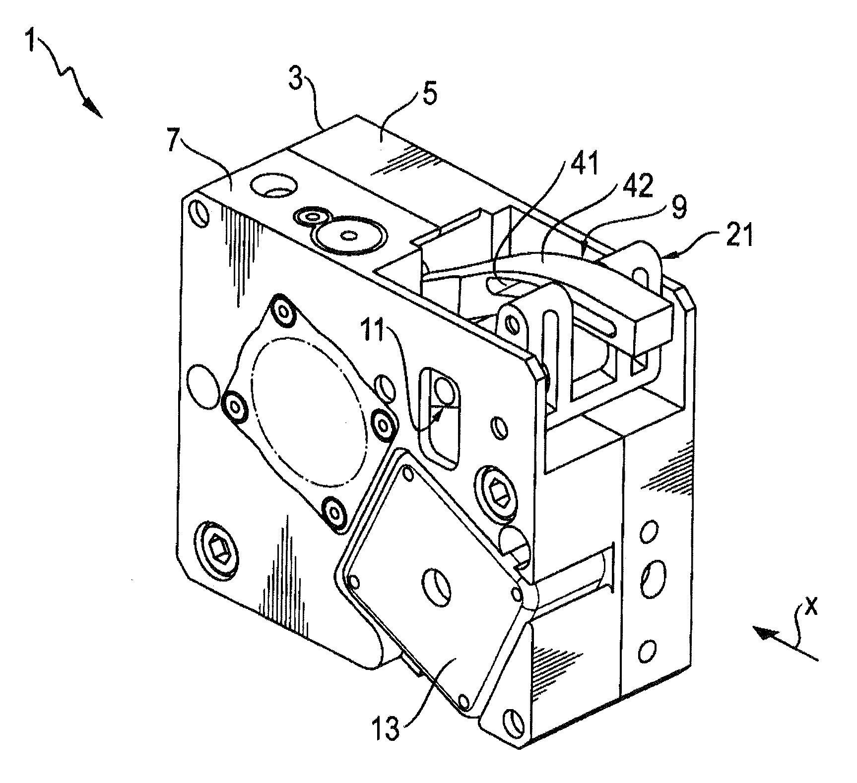
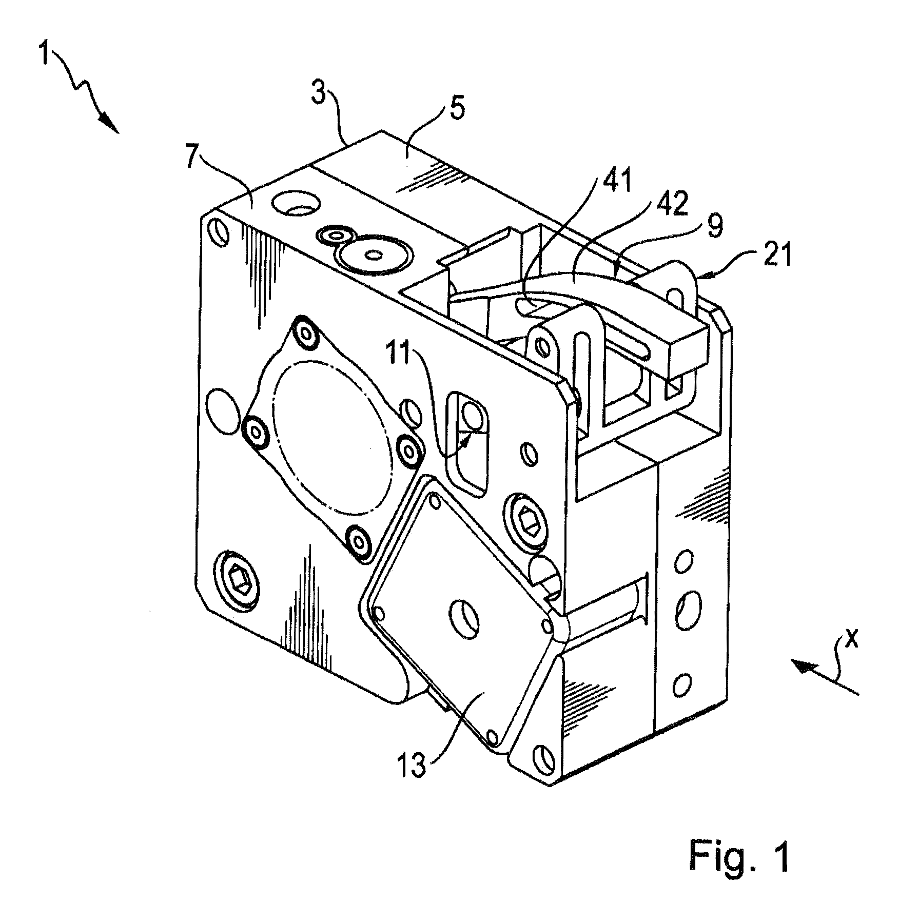
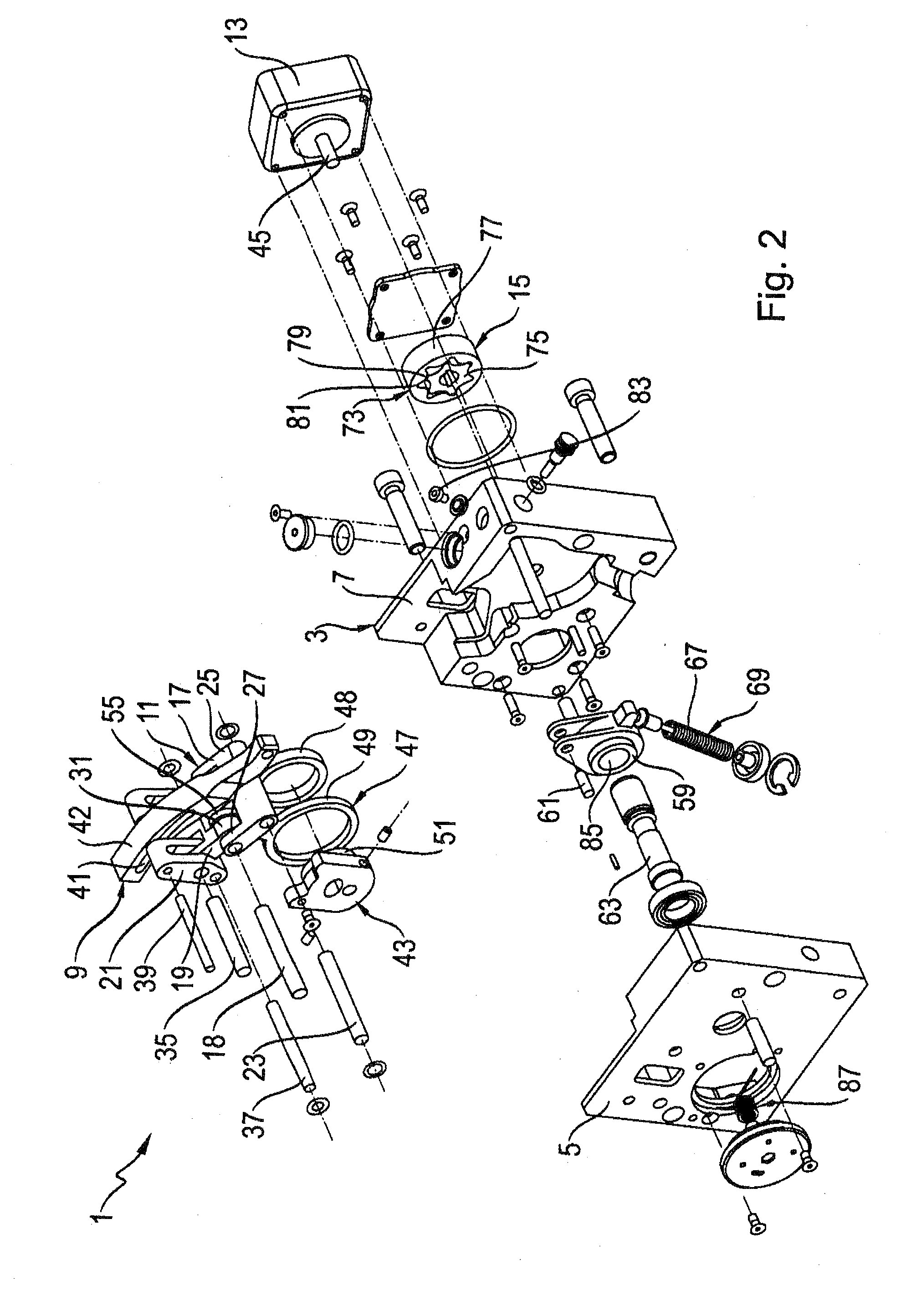
[0033]FIGS. 1 through 5 show a first exemplary embodiment of a stop module 1, which is used in particular in automated machining and conveyor systems, in order to separate objects, such as workpieces, workpiece holders, or the like, that are moving in a direction of motion X in a movement plane. After the objects have been separated, they can be individually handled, for instance machined, diverted, and so forth.

[0034]The stop module 1 is embodied with a base body 3, which is composed here of two base body elements 5 and 7. The stop module 1 furthermore has a stop element 9, which is provided for stopping or separating objects moving in the direction of motion X; the stop element 9 is movable by means of a toggle lever device 11 from a first terminal position, shown in FIG. 1 and protruding into the movement plane of the objects, into a lower, second terminal position that enables a motion of the objects both in the direction of motion X, and vice versa. For driving the toggle lever...


PUM


Abstract

A stop module has a base body, a stop element configured for objects moving in a direction of motion in a movement plane and located on the base body, a drive device for moving the stop element between a first terminal position, in which the stop element protrudes into the movement plane of the objects, and a second terminal position, in which the stop element enables a motion of objects in the movement plane, and a damping device cooperating with the stop element for damping a motion of the stop element from a first stop position into a second terminal stop position, which is offset relative to the first stop position at least approximately in the direction of motion of the objects, when an object is resting on the stop element, the damping device being configured so as to damp the motion of the stop element from the first stop position to the second terminal stop position with a rotation damper.

Description

CROSS-REFERENCE TO A RELATED APPLICATION[0001]The invention described and claimed hereinbelow is also described in German Patent Application DE 10 2007 062 075.8 filed on Dec. 21, 2007. This German Patent Application, whose subject matter is incorporated here by reference, provides the basis for a claim of priority of invention under 35 U.S.C. 119(a)-(d).BACKGROUND OF THE INVENTION[0002]The present invention relates to a stop module, in particular for automated machining and conveyor systems, in which a stop element for objects moving in a direction of motion in a movement plane is located on a base body.[0003]In automated machining and conveyor systems that are embodied for conveying objects, in particular workpieces or workpieces located on workpiece holders, it can be necessary for various reasons to stop the conveyance of the individual objects, in particular for performing machining operations on the workpieces during the standstill phase, but also for lifting the workpieces or...

Claims


Application Information

Patent Timeline
IPC IPC(8): B65G47/22
CPCB65G47/8823
Inventor LINDEMANN, UWELUDWIG, PETER
Owner ROBERT BOSCH GMBH
Learn More