Helicopter drip pan

a drip pan and drip technology, applied in mechanical equipment, manufacturing tools, transportation and packaging, etc., can solve the problems of fluid leaking into the helicopter cabin, the integrity of the sealing integrity of the peripheral seal used along the straight sealing surface is unacceptable, etc., and achieves the effect of minimal intrusion into the helicopter

Active Publication Date: 2009-06-25
PHOENIX PRODS
View PDF19 Cites 10 Cited by
  • Summary
  • Abstract
  • Description
  • Claims
  • Application Information

AI Technical Summary

Benefits of technology

[0024]Still another object of this invention is to provide a drip pan that can be attached to the existing structure of a BLACK HAWK®“M” model helic

Problems solved by technology

It was previously felt that peripheral seals used along straight sealing surfaces would provide unacceptable sealing integrity.
With this arrangement, flexure of the helicop

Method used


Image

  • Helicopter drip pan
  • Helicopter drip pan
  • Helicopter drip pan

Examples


Embodiment Construction

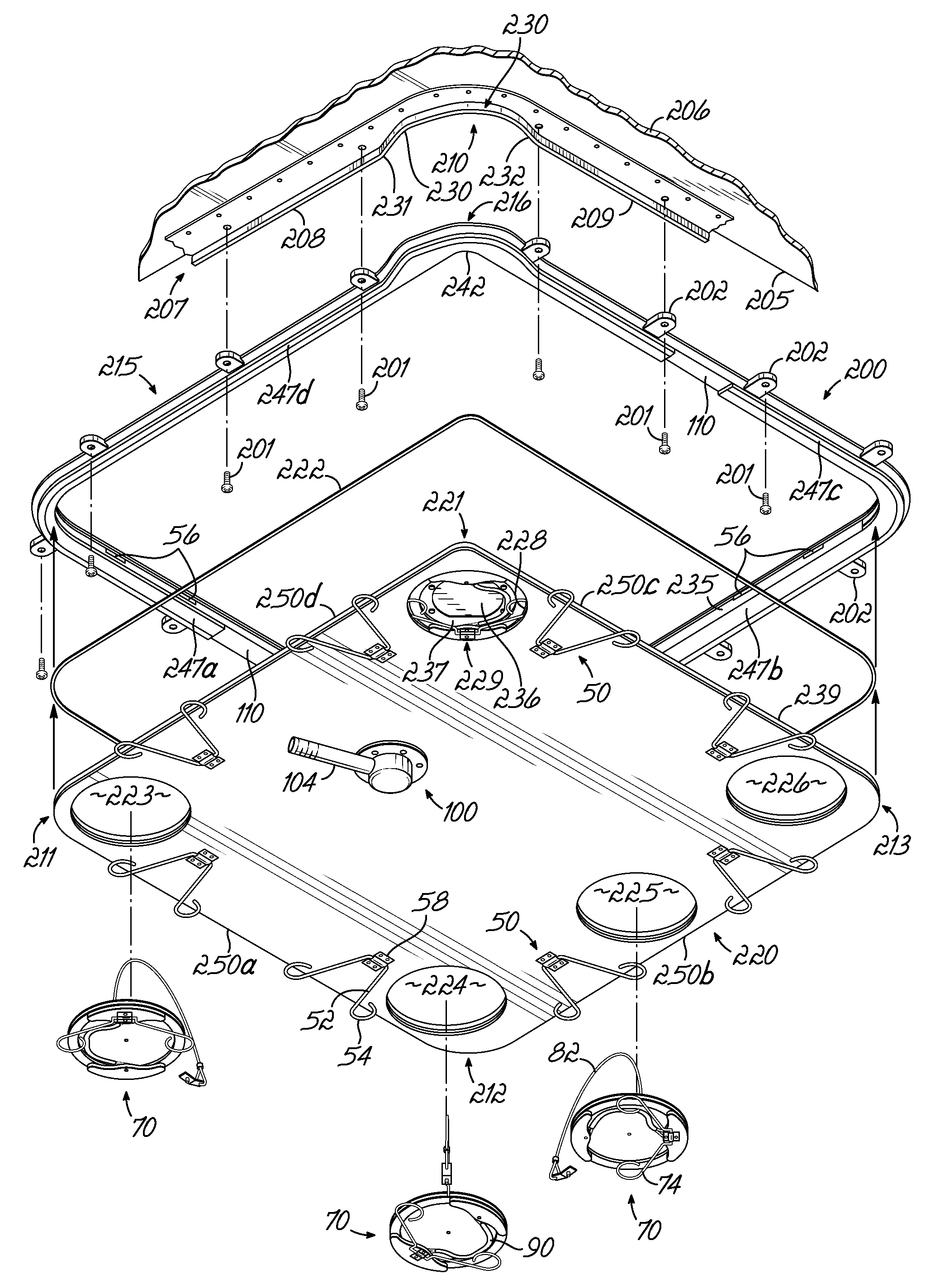
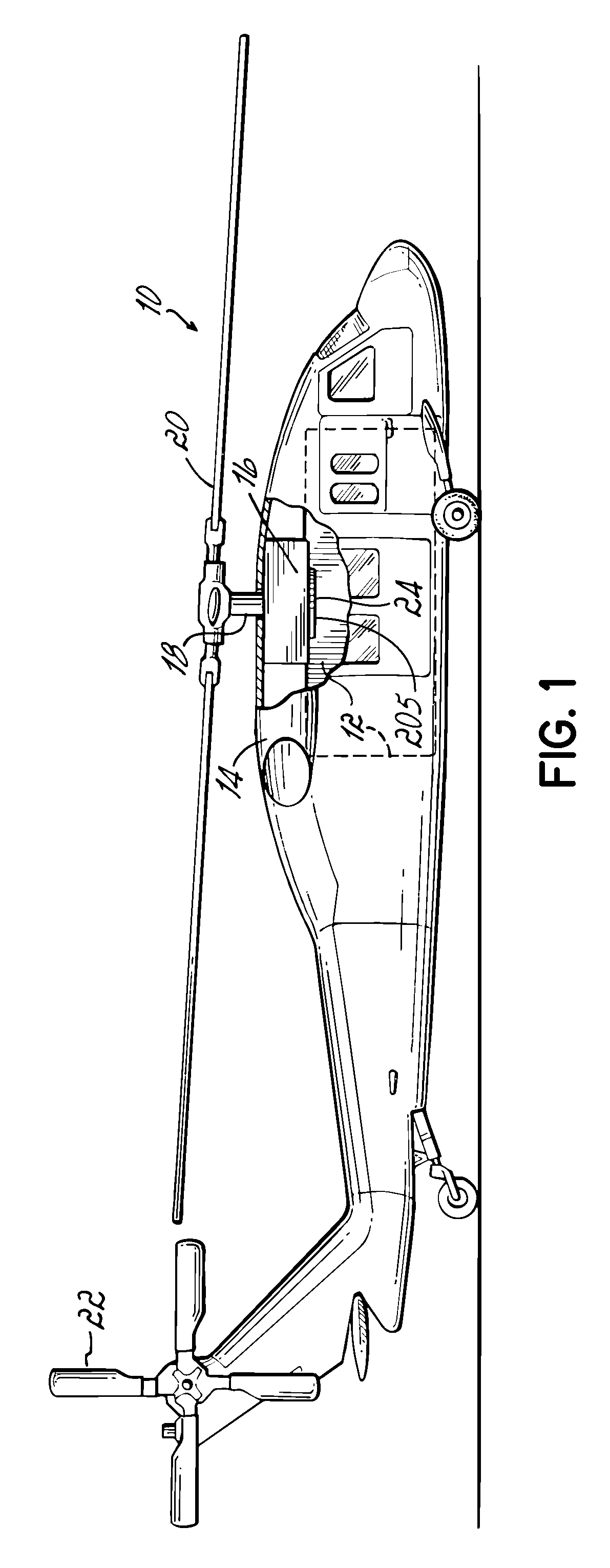
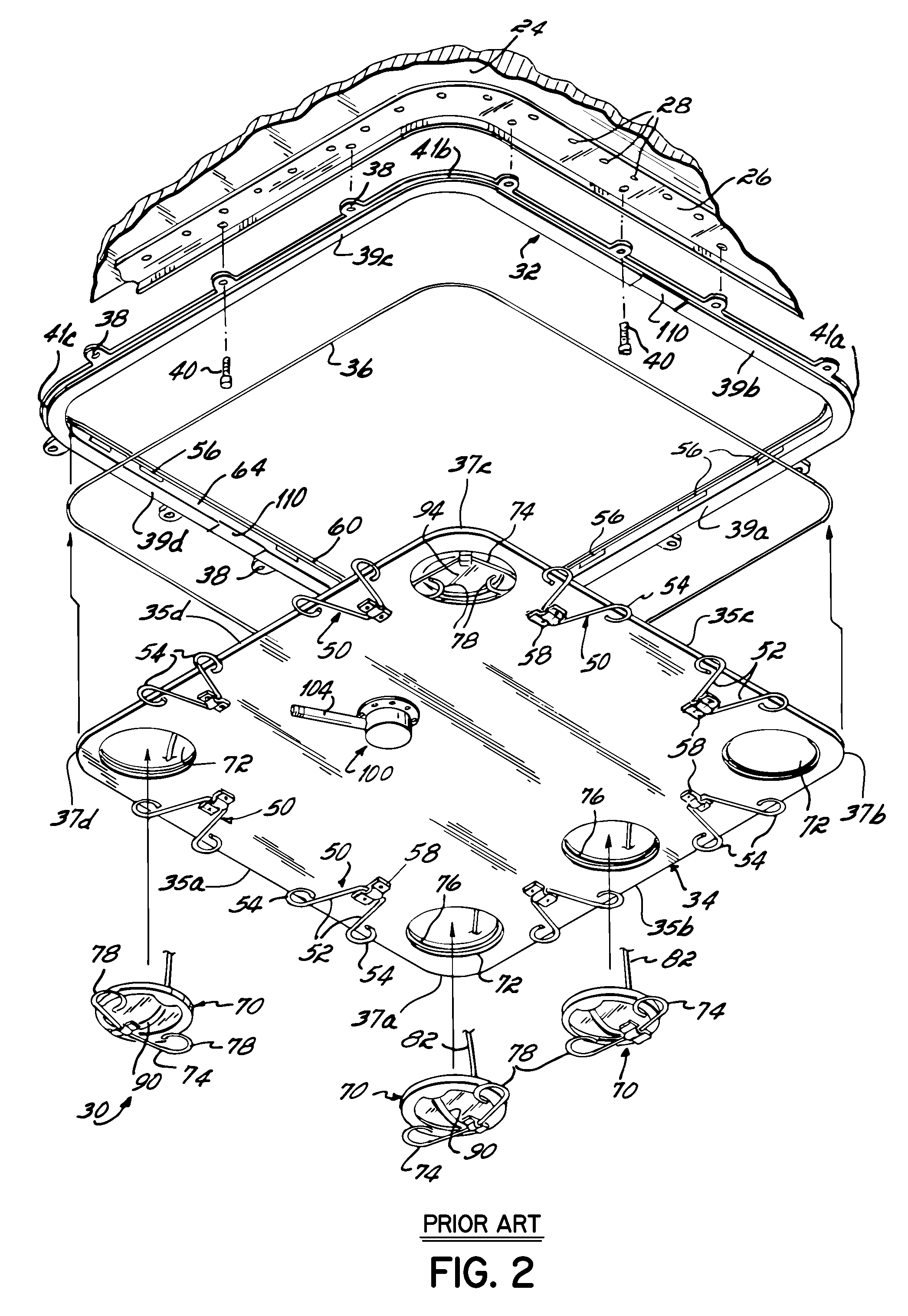
[0061]Embodiments of the invention described herein differ from that prior art of U.S. Pat. No. 6,446,907 (the '907 patent) in the structure of the elements defining the asymmetric corner components of a drip pan apparatus 200 shown in FIGS. 7-12. In other aspects, such as in materials of construction and function, in one embodiment, the drip pan apparatus 200 of this invention is like that described in said patent. Accordingly, any item numbers found in FIGS. 7-12 which are the same as those in FIGS. 2-6 designate like components. Moreover, the helicopter 10 of FIG. 1 is similar in outward appearance to the “M” model BLACK HAWK® helicopter and for that reason is used herein to illustrate an overall helicopter environment in which the new drip pan apparatus 200 of FIGS. 7-12 is used.

[0062]Turning to FIG. 1, there is shown therein a helicopter 10 representing generally for this invention a BLACK HAWK® Model “M” helicopter of the type made by the Sikorsky Aircraft Company of Stratford...


PUM

PropertyMeasurementUnit
Angleaaaaaaaaaa
Radiusaaaaaaaaaa
Widthaaaaaaaaaa

Abstract

A drip pan apparatus for a “M” model BLACK HAWK® helicopter and the like includes an expanded corner structure for accommodating an access port also positioned further outwardly in the corner than in prior drip pan apparatuses, facilitating filter viewing while retaining peripheral o-ring seal. An expanded corner of the airframe skirt is accommodated by the expanded corresponding corner of a frame, which also defines a small radius internal curve. The removable pan has a small radius curve cooperating with the small radius curve of the frame and is sealed thereto by the peripheral o-ring seal sealing the entire pan to the frame. Physical access to the filter is enhanced.

Description

CROSS REFERENCE TO RELATED APPLICATIONS[0001]This application claims the filing benefit of co-pending U.S. Provisional Application No. 61 / 014,960, filed Dec. 19, 2007, the disclosure of which is incorporated by reference herein in its entirety.FIELD OF THE INVENTION[0002]This invention relates to a fluid-tight drip pan, and more specifically to a fluid-tight drip pan for the engine or transmission compartment of a helicopter.BACKGROUND OF THE INVENTION[0003]Larger helicopters, in general, have several features in common in a typical basic configuration or layout. For instance, a typical helicopter will have a cabin section rearward of the pilot's cockpit or flight deck and which is used to transport people, cargo or both. In addition, the helicopter will have an engine compartment which is located typically above and to the rear of the pilot's cockpit or flight deck, and above the cabin section. The engine compartment typically houses two primary components, at least one engine and ...

Claims


Application Information

Patent Timeline
IPC IPC(8): F16N31/02B23P11/00B64C27/00
CPCF16N31/002Y10T29/49826Y10T29/49947
Inventor WILSON, THOMAS GRAY
Owner PHOENIX PRODS
Why Eureka
Try Eureka