Method and apparatus for bulk calibrating RFID tags

a radio frequency identification and bulk technology, applied in the field of radio frequency identification tags, can solve the problems of loss of transmitted power, critical concern, and inability to solve basic needs, and achieve the effect of avoiding unnecessary proliferation of numbers

Inactive Publication Date: 2009-06-25
RFMICRON
View PDF16 Cites 27 Cited by
  • Summary
  • Abstract
  • Description
  • Claims
  • Application Information

AI Technical Summary

Benefits of technology

[0043]I submit that each of these embodiments of my invention more efficiently calibrate self-tuning RFID tags than any prior art method or apparatus now known to me.

Problems solved by technology

Furthermore, it is of no relevance in such systems which specific voltage levels are selected to represent each of the logic states.
It is well known that mismatch between fC and fR results in loss of transmitted power.
In some applications, this may not be of particular concern, but, in others, such as in RF identification (“RFID”) applications, such losses are of critical concern.
Although it would be highly desirable to have a single design that is useful in all systems, one very significant issue in this regard is the diversity of international standards as to appropriate RFID system frequencies, and, to the extent there is any de facto standardization, the available frequency spectrum is quite broad: Low-Frequency (“LF”), including 125-134.2 kHz and 140-148 kHz; High-Frequency (“HF”) at 13.56 MHz; and Ultra-High-Frequency (“UHF”) at 860-960 MHz.
However, such structural improvements, while valuable, do not solve the basic need for a variable impedance circuit having a relatively broad tuning range.

Method used


Image

  • Method and apparatus for bulk calibrating RFID tags
  • Method and apparatus for bulk calibrating RFID tags
  • Method and apparatus for bulk calibrating RFID tags

Examples


Embodiment Construction

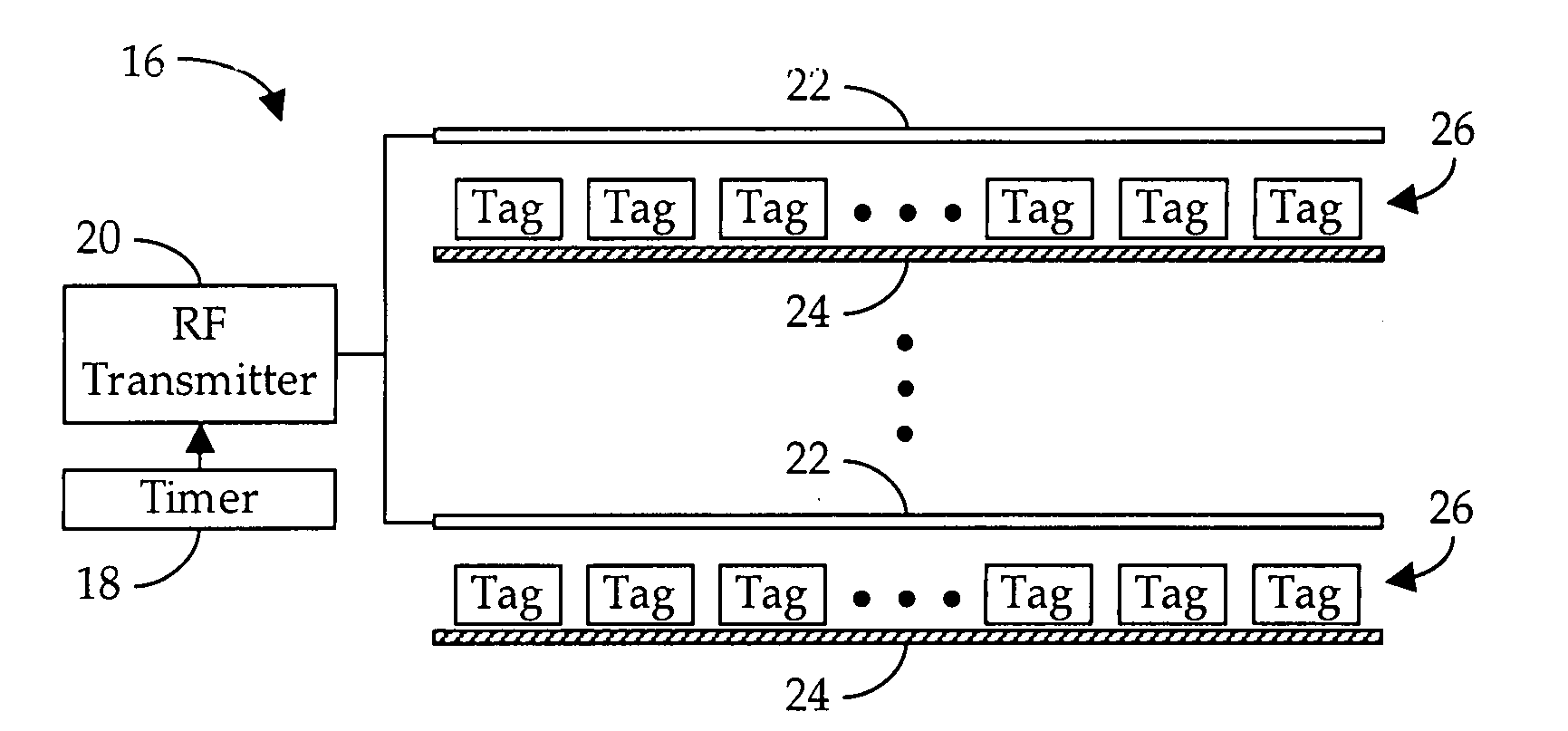
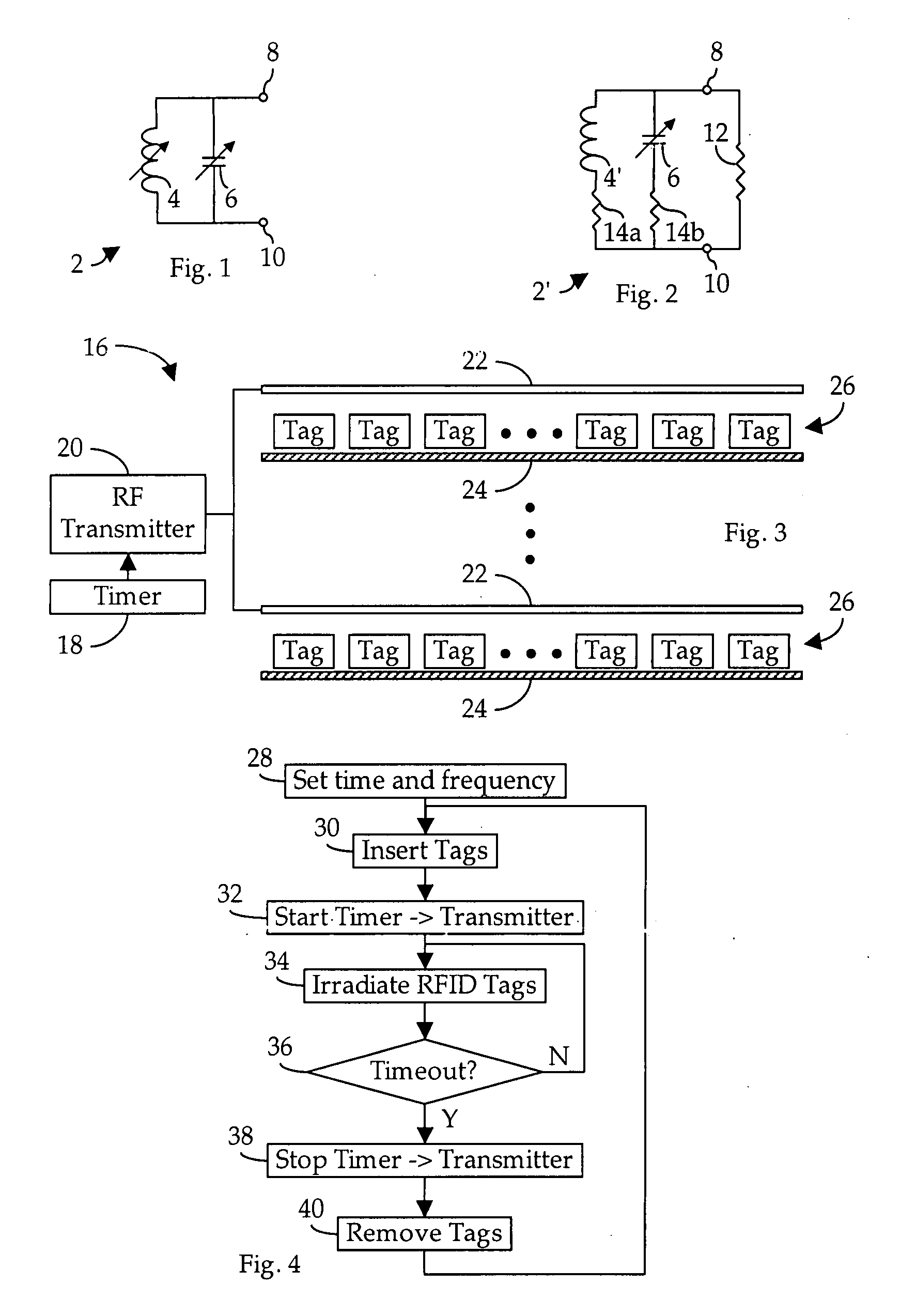
[0050]Shown in FIG. 3 is a bulk calibration system 16 constructed in accordance with the preferred embodiment of my invention. In the calibration system 16, a timer 18 selectively enables an RF transmitter 20 to broadcast, via an antenna 22, an RF signal, the carrier frequency of which is selected within one of the established RFID system operating frequency ranges, as discussed above. For example, within the low-frequency (“LF”) range of 125-134.2 kHz, a frequency of around 125 kHz would be appropriate; whereas, for the high-frequency (“HF”) range, 13.56 MHz would be appropriate; and, for the ultra-high-frequency (“UHF”) 910 MHz would be appropriate. Of course, other frequencies may be appropriate for specific applications or for tags intended for use in countries having specified standards for such tags.

[0051]A structure 24, such as a tag carrier tray or the like, is provided to support a plurality of conventional self-tuning RFID tags 26. In general, each of the tags 26 is design...


PUM


Abstract

A method and apparatus for bulk calibrating self-tuning radio frequency identification (“RFID”) tags wherein a plurality of the tags are simultaneously exposed to a broadcast RF signal of sufficient strength and for a sufficient period of time to assure self-calibration of all tags.

Description

BACKGROUND OF THE INVENTION[0001]1. Field of the Invention[0002]The present invention relates generally to radio frequency identification tags, and, in particular, to a method and apparatus for bulk calibrating radio frequency identification tags.[0003]2. Description of the Related Art[0004]In general, in the descriptions that follow, I will italicize the first occurrence of each special term of art which should be familiar to those skilled in the art of radio frequency (“RF”) communication systems. In addition, when I first introduce a term that I believe to be new or that I will use in a context that I believe to be new, I will bold the term and provide the definition that I intend to apply to that term. In addition, throughout this description, I will sometimes use the terms assert and negate when referring to the rendering of a signal, signal flag, status bit, or similar apparatus into its logically true or logically false state, respectively, and the term toggle to indicate the...

Claims


Application Information

Patent Timeline
Patent Type & Authority Applications(United States)
IPC IPC(8): G08B13/14
CPCG06K19/0726G06K19/0723
Inventor ROKHSAZ, SHAHRIAR
Owner RFMICRON
Why Eureka
Try Eureka