Input device and control method using input device

a control method and input device technology, applied in the field of input devices, can solve the problems of power consumption increase, detection accuracy degrade, offset drift, etc., and achieve the effect of efficient execution of offset calibration

Active Publication Date: 2015-06-11
ALPS ALPINE CO LTD
View PDF4 Cites 12 Cited by
  • Summary
  • Abstract
  • Description
  • Claims
  • Application Information

AI Technical Summary

Benefits of technology

[0018]With the input device, and the control method using the input device according to the aspect of the present invention, it is possible to efficiently execute the offset calibration for the load detection sensor by using input operation information resulting from the output of the position detection sensor.

Problems solved by technology

However, Japanese Unexamined Patent Application Publication Nos. 9-146689 and 8-328727 do not disclose an input device including a capacitance sensor, and a force sensor that measures pressing force.
Incidentally, there is a problem in that an output of the force sensor causes offset drift due to a change in a stress applied to a device with an input device, a change in a temperature, a change in a device shape over time, or the like.
Accordingly, the force sensor is not accurately driven, detection precision is degraded, and power consumption increases.

Method used


Image

  • Input device and control method using input device
  • Input device and control method using input device
  • Input device and control method using input device

Examples


Embodiment Construction

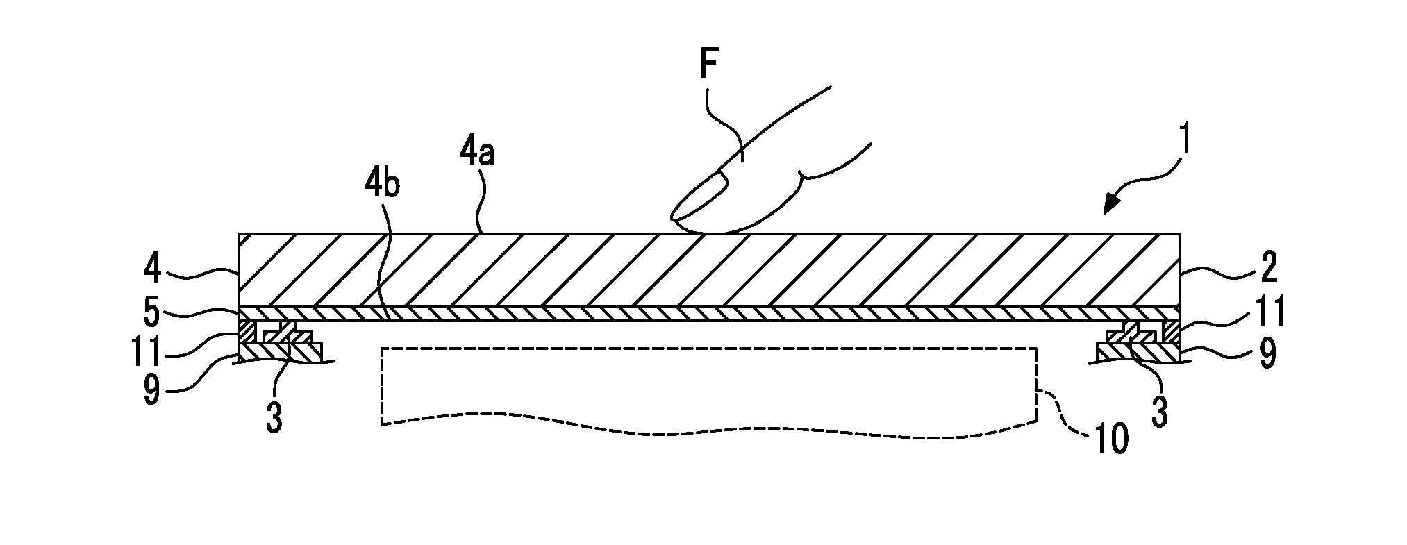
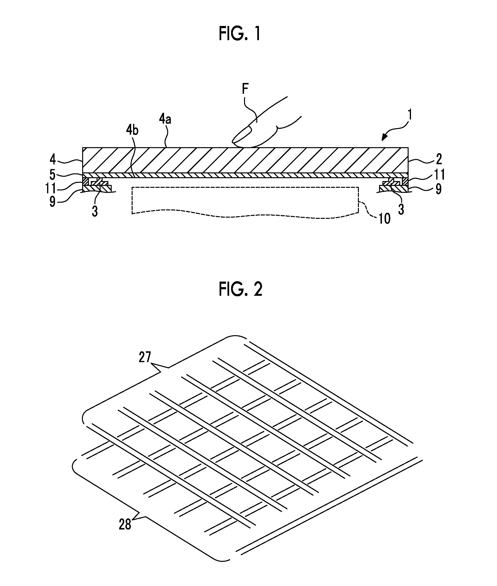
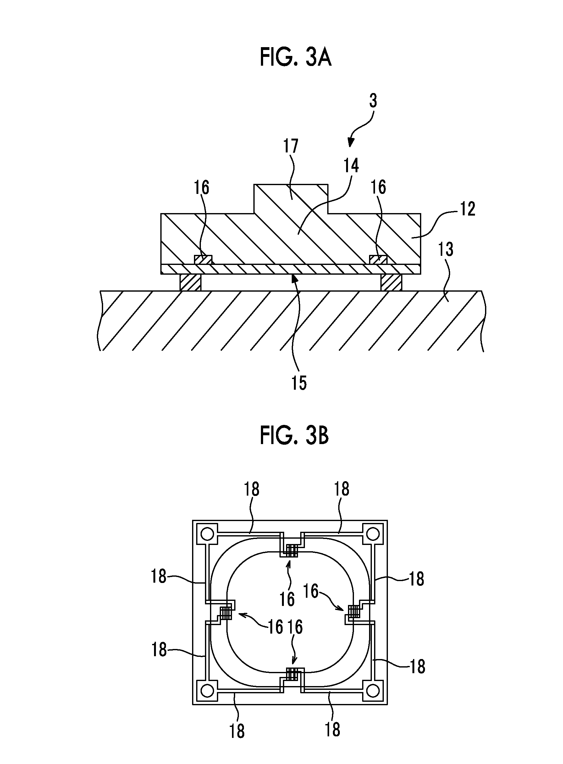
[0027]FIG. 1 is a partial longitudinal sectional view of an input device (touch panel) in an embodiment of the present invention, FIG. 2 is an illustrative diagram of a capacitive touch panel sensor, FIGS. 3A and 3B are illustrative diagrams of a load detection sensor (force sensor), FIG. 3A is partial longitudinal sectional view, FIG. 3B is a back perspective view of a sensor substrate constituting the load detection sensor, and FIG. 4 is a plan view of an input device of this embodiment.

[0028]The input device (touch panel) 1 in this embodiment includes a plurality of load detection sensors (force sensors) 3 on the back surface side of a capacitive touch panel sensor (position detection sensor) 2.

[0029]The capacitive touch panel sensor 2 is configured to include a transparent operation panel 4, and a sensor layer 5 provided on a back surface 4b of the operation panel 4, as illustrated in FIG. 1. The operation panel 4 is formed of glass, plastic, or the like. A surface of the operat...


PUM


Abstract

An input device includes a position detection sensor capable of detecting an input operation position of an operation body on an operation surface, a load detection sensor capable of detecting a load in the input operation position, and a control unit capable of executing offset calibration to correct an offset of an output of the load detection sensor based on input operation information resulting from an output of the position detection sensor.

Description

CLAIM OF PRIORITY[0001]This application is a Continuation of International Application No. PCT / JP2013 / 076982 filed on Oct. 3, 2013, which claims benefit of Japanese Patent Application No. 2012-222619 filed on Oct. 5, 2012. The entire contents of each application noted above are hereby incorporated by reference.BACKGROUND OF THE INVENTION[0002]1. Field of the Invention[0003]The present invention relates to an input device mounted on a portable device or another electronic device and operated by causing an operation body such as a finger to come into contact with an operation panel.[0004]2. Description of the Related Art[0005]Japanese Unexamined Patent Application Publication No. 2009-87311 discloses an input device that detects a movement position using a capacitance sensor and detects an amount of pressing using a distortion sensor.[0006]Further, Japanese Unexamined Patent Application Publication No. 2010-211399 discloses an information processing device having a pressure sensor and...

Claims


Application Information

Patent Timeline
Patent Type & Authority Applications(United States)
IPC IPC(8): G06F3/041G06F3/044
CPCG06F3/0418G06F3/0414G06F2203/04106G06F2203/04105G06F3/044G06F3/041
Inventor KANEKO, MASAFUMIISHIZONE, MASAHIKOSATO, TAKASHIUMETSU, EIJI
Owner ALPS ALPINE CO LTD
Why Eureka
Try Eureka